Residual stresses and cutting forces in cryogenic milling of Inconel 718
2020-05-18
Abstract
Due to its excellent mechanical and corrosion resistance at high temperatures, the Inconel 718 alloy has several applications in the aerospace and nuclear industries. The microstructure of this material acquires rapid hardening during machining and its low thermal conductivity contributes to high temperatures in the cutting zone. As the temperature increases, the cutting tool wear accelerates, compromising the final quality of the machined part. These factors turn Inconel 718 a difficult-to-cut material and generate residual stresses due to thermal and mechanics loads during machining. The cutting fluids purpose is to cool and lubricate the process, as well as to remove the chip from the cutting zone. Liquid nitrogen (LN2) was used to meet the gap of research involving residual stresses analysis in cryogenic machining. This study presents an experimental analysis of the Inconel 718 end milling on the residual stresses generation, cutting forces, tool wear and surface integrity of the machined workpiece. The results were compared to a previous study concluding that the fluids did not influenced the cutting forces levels, and the results with LN2 were increasing along the cutting length. The cryogenic method presented low residual stresses levels and improved workpiece surface roughness compared to flood method, although the flood method contributed for compressive residual
stresses, which may be beneficial to the service life of the machined component.
1. Introduction
Inconel 718 is a heat-resistant nickel super alloy with excel- lent mechanical strength at elevated temperatures and high corrosion resistance. Due to its excellent properties: creep and fatigue resistance at high temperatures, good corrosion resistance and good weldability, it is used in combustion chambers and blades and all the components of the hot section of gas turbine engines. Inconel 718 presents good ductility at cryogenic temperatures, and for this reason it is well machined with liquid nitrogen to reduce the high temperatures in the cutting zone caused by the low conductivity of this material. Le Coz and Dudzinski claimed that a moderate cutting temperature and low thermal shock could reduce tool wear. In the past decades, various methods of cooling have been proposed, including minimum quantity lubrication (MQL) and cryogenic cooling, as detailed by Sharma et al. Shokrani et al. studied milling Inconel with cryogenic cutting fluid that provided roughness reduction compared to dry cutting, although tool life reduced significantly. The influence of cryogenic cutting on milling of Inconel 718 was also studied by Aramcharoen and Chuan and compared with flood and dry cutting. The cryogenic method significantly reduced the temperature in the shear zone and improved cooling at the chip- tool interface compared to the flood. The friction of the chip-tool contact was reduced and the lubrication was efficient with the cryogenic cooling, reducing the wear of the tool, improving the quality of the machined surface and allowing the increase of the cutting speed. The machining force components presented higher levels, in ascending order, for flood, cryogenic and dry cutting.
Lequien, P et al investigated the thermo mechanical phenomena in interrupted cutting of Ti6Al4V alloy under cryogenic, flood cooling and dry conditions using a special designed experimental setup. This work highlights the influence of cryogenic flow rate and cutting time/non-cutting ratio on tool temperature. Also Tahri et al developed a CFD model is developed and applied to investigate the liquid nitrogen (LN2) flow inside the pipe connecting the reservoir to the cutting tool/nozzle. The results show that the effectiveness of the cooling process depends not only on the input flow parameters (pressure, velocity, temperature and gas/liquid fraction), but also on the pipe geometry. Although, it was not found studies presenting residual stress analysis comparing flood and cryogenic machining. In the present study article, are compared the results of machining forces, residual stresses and hardness in end milling of Inconel 718 using three types of cutting methods: flood, minimum quantity of minimum quantity of lubricant (MQL) and cryogenic cutting using liquid nitrogen (LN2) to reduce the workpiece temperature during cutting.
2. Cutting Force and Residual Stress
The machining force of one cutting edge in milling is usually decomposed in tangential, radial and vertical components. When only one insert is cutting the workpiece at a time, tangential and radial forces could be identified using the measured forces in dynamometer referential and insert angle position ϕ. It is the case for two inserts located in opposite sides in the tool holder. Also, if the helix angle is low (λh 0), the vertical component can be neglected. The tangential cutting force Fc and radial force Fr can be modeled using Martellotti equation, as a function of specific cutting force kc (N/mm2), radial cutting pressure kr (N/mm2) and the area defined by depth of cut ap and uncut chip thickness:
Fc = kc.ap. ft.senϕ→Fc(ϕ = 90o) = FT = kc.ap. ft (1)
Fr = kr.ap. ft.senϕ→Fr(ϕ = 90o) = FL = kr.ap. ft (2)
In Figure 1 it can be identified the point (1) where the chip load is maximum and the cutting force is higher. In this point, tangential force can be called transversal force FT and radial force is placed in longitudinal direction FL. This is important, as those are the common directions for residual stresses measuring.
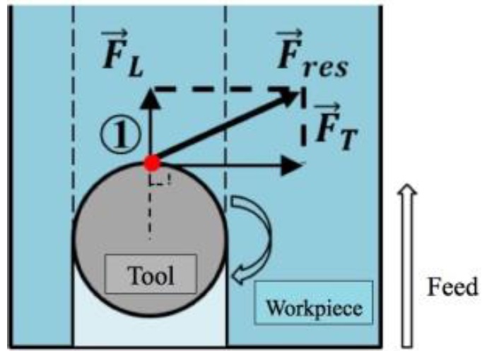
Fig. 1. Longitudinal Force FL (Radial Force) and Transversal Forces FT (Cut-ting Force) in Point (1)
In general, the cutting process generates compressive residual stresses when tool-chip interface produces shear deformation in the workpiece and tensile residual stresses if it is related to heat exchange in the workpiece. For example, the increasing the cutting speed results heat generation increasing and compressive residual stresses reduction. In this case, the force could be lower as the specific cutting force tends to reduce. Considering only the use of cutting fluids and maintaining the cutting speed, the presence of tensile residual stresses are associated to the wear and the heating of the tool-workpiece interface. In this article, forces and residual stresses are taken in longitudinal and transversal directions in the middle of the channels in order to identify this relationship.
3. Materials and Methods
In the present work, the Inconel 718 was supplied as a 90 mm bar welded underneath for fixation in the dynamometer. Its chemical composition, according to ASTM B 637 - 06 (2003) in % weight: Ni (50-55%); Cr (7-21%); Nb (4.8-5.5%); Mo (2.8-.3%) other elements 0.3 each. The surface was flatted and remachined after all residual stress and surface measurements, when it was needed. The CNC machine tool Romi Polaris V400 with Fanuc CNC is used in cutting experiments, as shown in Figure 2. A 16 mm diameter is used with an insert coated with TiAlN. This insert presents a 0.8 mm corner radius, so it is defined 1mm of constant depth of cut in all experiments. The cutting speed and feed per tooth was defined according to previous study as 20 m/min and 0.04 mm/th, respectively. The experiments were conducted producing channels in full machining and analyzing the tool wear each 10 mm without removing the tool holder from the machine tool.
The study is focused in three methods of cutting fluid application: flood, MQL and cryogenic fluid in workpiece (Fig. 2c and 2d). The cutting fluid (Balxedot), supplied by Baltar Quimica, is a vegetable-based oil, a soluble fluid including ethanol and soy oil. It was diluted in a 1:40 ratio with potable water and used in both cutting fluid application methods: flood and MQL. For MQL it was used a Kool Mist nozzle with magnetic support. The adjustable nozzle allows control of the cutting fluid flow to 1100 mL/h, through the compressed air inlet valve and to- wards the cutting zone as described in. The cryogenic fluid is supplied by a 50 liter Dewar reservoir with a manometer to keep 5 bar pressure and a metallic hose. The workpiece temperature is measured using a thermocouple, Agilent 34970A signal amplifier and A/D acquisition board USB-6251.
%20Machine%20Tool%20and%20Equipment.jpg)
%20Machine%20Tool%20and%20Equipment2.jpg)
%20Machine%20Tool%20and%20Equipment3.jpg)
%20Machine%20Tool%20and%20Equipment4.jpg)
Fig. 2. (a) Machine Tool and Equipment using LN2 (b) Tool Wear Measurement (c) MQL System (d) LN2 nozzle and thermocouple (e)Residual Stress Measurement (f) Roughness Measurement
The digital microscope Dino-Lite model AM4115T was used to capture tool wear images. The tool returns to this position for tool wear analysis after each cutting step. It was used a Kistler dynamometer (9257 BA) with a signal amplifier (5070) and an A/D data acquisition board (National Instruments USB- 6551). It was analyzed the longitudinal and transversal force in point (1) described in Figure 1 and the resultant machining force. Surface residual stresses were analyzed by the X-ray diffraction technique, using the sin 2ψ method. The measurement used the following set-up: Ni as diffracted material, diffracting plane=(311), CrKβ radiation, wavelength of 2.0848 Å, Bragg angle of 157.73o and inclination angle ψ = 0, 18, 27, 33 and 45o. The stress measurement was performed in a modern Xstress 3000 portable (Fig. 2e), with a collimator of φ 1.0 mm, (30 kV and 6.7 mA). The software XTronic V1-0 Standard was used to perform the stress calculation. The hardness test equipment was an Indentec ZHU250CLS using a Brinell indenter with 1mm sphere at a 294.2 N load for 10s.
4. Experimental Results
The machining force of one cutting edge in milling is usually decomposed in reduced tool wear is of significant importance in machining Inconel 718, due to its low thermal conductivity, which causes reduced heat dissipation in the cutting area. Figure 3 presents the results of tool wear in all experiments using different lubricant application methods. Two curves are presented for each case: one for insert A and other curve insert B of the tool holder. New inserts were used for each cutting fluid method.
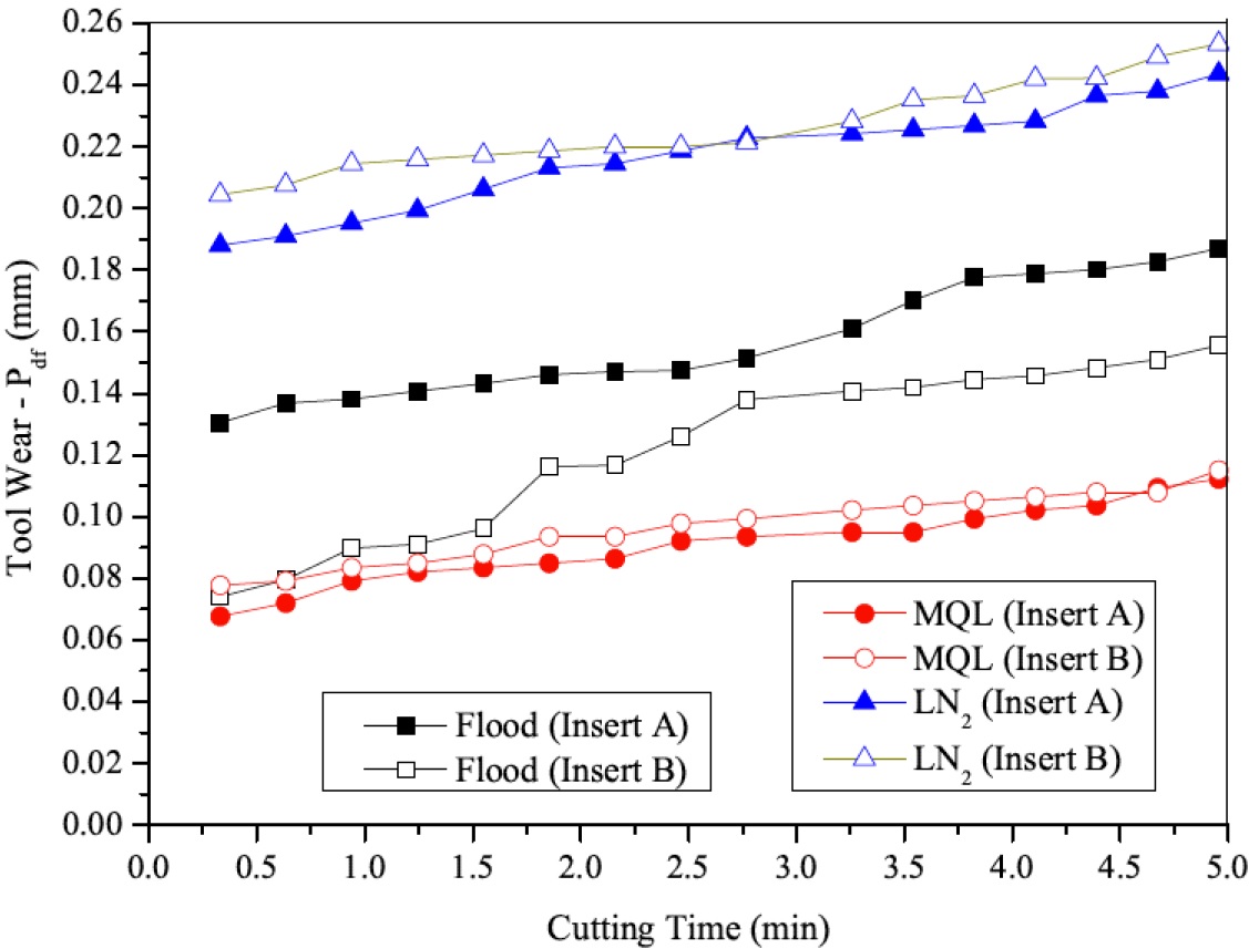
Fig. 3. Tool Wear Results
The tool-wear results show that the MQL condition achieved lower values of wear compared to flood and cryogenic cutting. Thakur and Gangopadhyay have recently shown that an increase in flow rate of MQL might be associated with less tool wear. Fig. 4 shows transversal and longitudinal maximum force calculated on each 2 mm of cutting length. Residual stress results in longitudinal direction (Fig. 5) shows a pattern, where in transversal direction there is no standard behavior in full milling. As established by Withers and Bhadeshia, compressive residual stresses are beneficial for increasing workpiece fatigue life. It is reasonable to con- sider that flood cutting method is better in this approach and that MQL produces compressive stresses until 80mm. LN2 due to its higher heat exchange with workpiece, produced only tensile stresses, which it could be a problem depending on its use. The hardness test results presented in Fig 5 shows that the values are still inside the expected values. The horizontal dashed lines in the graph indicate the upper and lower limits of the theoretical value of Brinell hardness for Inconel 718.
Fig. 4. Force Results (a) Transversal (b) Longitudinal (Maximum Force in each 4 mm)
.jpg)
Fig. 5. Residual Stress Results (Longitudinal) – Measured points along the channel
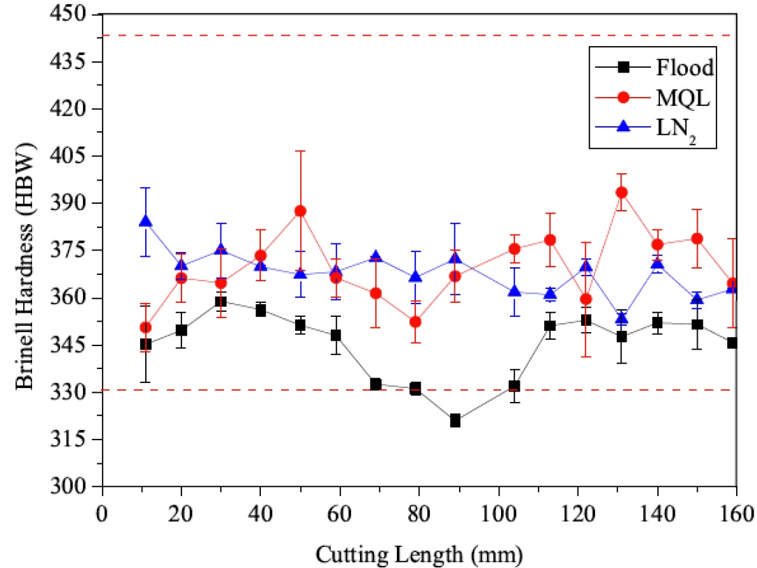
Fig. 6. Hardness Results
5. Conclusions
This study compares the influence of cryogenic cutting fluid, MQL and flood methods on end milling the Inconel 718 alloy and it can be concluded that:
• The constant wear rate in curves indicates that the tools did not reach their tool life, but under the studied wear level, the MQL technique provided the lowest levels of wear for the same cutting conditions;
• The resulting force levels were similar in both methods flood and MQL using water based cutting fluid, nevertheless using liquid nitrogen about 15% higher increasing in the last experiments;
• The longitudinal residual stresses generated at the beginning of channels are compressive in all cases and after tool wear, it became tensile except in flood. It can be claimed that the tool wears leaded to higher forces along the cutting length with tensile residual stresses;
• The correlation between longitudinal residual stresses and machining forces indicated that tensile stress are promoted by the increasing of machining forces;
• The cutting fluids methods did not influence significantly the hardness of the machined material.
Acknowledgements
The authors would like to thank the Brazilian research agencies CNPq, CAPES and FAPERJ, for their financial support.