Cutting performance of solid ceramic and carbide end milling tools in machining of nickel based alloy Inconel 718 and stainless steel 316L
2020-06-03
Abstract
Machining of nickel based alloys is in most of the times affected via high mechanical and thermal loads, causing high wear tendency of carbide tools, even at relatively low cutting speeds. On the other hand, ceramic as a cutting material, is more chemically stable and retains its hardness even at higher temperatures (> 800 °C) when machining difficult‐to‐cut materials. Therefore, to increase productivity, as an alternative to carbide tools, full body ceramic milling tools are proposed. In this paper, high speed milling process, using full body ceramic end milling tools, was analyzed in parallel to carbide tools. Tool life of ceramic tools was compared with tool life of more widely used carbide tools when milling two different difficult‐to‐cut materials, i. e. nickel based alloy Inconel 718 and austenitic stainless steel 316L, under different cooling lubrication conditions. In addition, surface integrity and cost analysis were taken into account. Results are showing that ceramic milling tools are increasing material removal rate and productivity. However, the overall efficiency of ceramic tools can still be economically questionable.
1. Introduction
Nowadays, we are increasingly focused on the sustainability of machining processes, trying to avoid conventional machining where oil based cooling lubrication fluids (oilCLFs) are used. Those are increasing manufacturing expenses and are known to be one of the contaminants in environment, as well are harmful to human’s health. Therefore, significantly cleaner and more environmentally friendly machining process would be dry machining. However, lack of cooling and lubricating effect, especially when machining difficult‐to‐cut materials, can reflect in high temperatures in the cutting zone, which shorten tool life and decrease productivity. In such cases, one of the options to increase productivity is to use other cooling lubrication techniques, such as cryogenics, or different tool materials, as ceramic, which can withstand higher temperatures then widely used carbide tools.
Ceramic, as a cutting material, appeared relatively early (in 1935, USA), but its use was not economically justified until the 1960s. Ceramics main advantage is that it is stable even at high temperatures and in such retains its hardness (high compressive strength), has a good wear resistance and is chemically stable at elevated temperatures. To manufacture ceramic end milling tools, sintering manufacturing process is used. The fine‐grained powder is pressed under high pressure and bounded at temperatures between 1200‐1800 °C. Properties of the ceramic tools depend of the composition, the density of the structure, size and distribution of the grain and the sintering temperature. Due to these unique ceramic properties, ceramic tools are mainly used for machining of difficult‐to‐cut materials, primarily thinking of titanium and nickel based alloys that are unable to be machined with carbide tools without oilCLFs. An additional advantage of ceramic tools is that the cutting speed is three to ten times higher as at carbide tools, which contributes to a higher material removal rate (MRR) and consequently higher productivity. However, researches marked poor resistance of ceramic tools to dynamic mechanical stress, as main disadvantage of these tools.
Narutaki et al. were observing tool wear of three different ceramic tools when turning Inconel 718. They realized, if they use lower cutting speeds (100‐300 m/min), best durability offers ceramic Al2O3 with added silicon carbide. If, however, the cutting speed is raised to a 500 m/min, more durable tool turns to be Al2O3 with added TiC. They have explained this by diffusivity tests and temperature measurements. When machining with high cutting speeds, flank face has reached 1250‐1300 °C, while the melting point of the Inconel 718 is 1550 °C. At such high temperature, diffusion is evident; when using ceramic tool with added SiC, diffusion of nickel from the workpiece material into the tool occurs. When using Si3N4 ceramics, silicon passes into Inconel 718 and chromium backwards into the tool. They marked Al2O3‐TiC tool as most stable tool in such working conditions. Kitagawa et al. also came to the same conclusion.
Performances of ceramic tools reinforced with SiC, when milling Inconel 718, were researched by Elbestawi et al. They noticed three types of tool wear: (i) abrasion on the flank face, (ii) notch wear and (iii) the cavity on the rake face. Notch wear was the main reason for the tool failure when milling at full depth, with cutting speeds from 200 to 400 m/min. When milling with higher cutting speeds (400‐700 m/min) and a smaller depth of cut, flank wear and wear on the secondary edge were the most dominant.
Li et al. have analyzed performance of SiAlON ceramic tools (Si3N4‐Al2O3) when turning Inconel 718. For SiAlON ceramic tools notch wear with minimal damage of the cutting edge at low cutting speed (120 m/min) is noticeable. That begins to change at 240 m/min. When the speed is increased to 300 m/min, it is already possible to see a decrease in the notch formation and increase in flank wear.
From most of published scientific researches, it has been observed that removable ceramic cutting tools – inserts were used. There are only a few scientific studies in which full body ceramic cutting tools were used. The reason for this lies in the complex manufacturing processes of ceramic rods and in complex grinding processes to manufacture full body ceramic tools. Some improvements on this field are presented in a paper of Uhlmann and Hubert, where proved that the nature of these ceramic cutting tools heavily depends on its composition.
Celik et al. investigated wear mechanisms of solid SiAlON ceramic tools when milling Inconel 718. They showed that there were present severe adhesion of workpiece and formation of diffusion layer due to chemical interaction of the tool flank face and the workpiece. Additionally, high operating temperature of the tools (>1000 °C) was observed. It was found that thermal expansion coefficient of the diffusion layer on the tool is lower than expansion coefficient of the tools material. Therefore, thermal micro cracks were formed causing tool wear.
Wang and Liu made another study on full body ceramic tools, where they investigated cutting performances of different solid ceramic end milling tools in comparison with carbide tool in machining hardened AISI H13 steel. They came to conclusion that cutting forces of ceramic end milling tools are lower than that of the carbide tool, mainly due to low chemical activity of ceramic with workpiece material. Overall, Ti(C, N) ceramic end milling tools present best cutting performance considering cutting forces, surface quality and tool life.
Many industrial applications demand machining process to be carried out in tight and narrow pockets and this can be only done with usage of solid end milling tools. According to the above presented review on the state of the art, it can be found that most of the studies were performed on the Inconel 718, as workpiece material, and with usage of ceramic cutting inserts, as a cutting tool. Moreover, there is a lack of studies using full body ceramic tools. To fulfil that gap, authors performed preliminary experiments using full body ceramic milling tools in machining of Inconel 718, where they confirmed their suitability for milling of Inconel 718. Their cutting performance, when machining other workpiece materials, and their cost efficiency, in comparison to conventional carbide tools, were still questionable. Thus in this paper, full body ceramic end milling tools were used to machine two difficult‐to‐cut materials, i. e. nickel based alloy Inconel 718 and austenitic stainless steel (SS) 316L, under different cooling lubrication conditions. Focus is placed on analysis of tool wear, tool life, workpiece surface and nevertheless, the productivity and costs.
2. Materials and methods
2.1 Workpiece materials
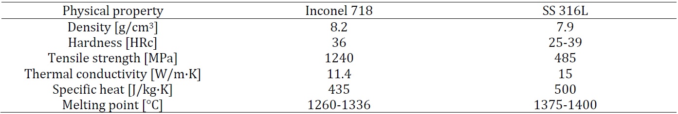
Difficult‐to‐cut nickel based alloy Inconel 718 and austenitic stainless steel (SS) 316L in the form of rods, with a diameter of 50 mm and a length of 200 mm, were used as a workpiece materials. Physical properties of both materials are presented in Table 1. Properties as high melting point, heat and wear resistance and high hardness at room temperature, are causing difficulties in machining operations.
Nickel based alloy Inconel 718 is used in the most demanding operating conditions, in the presence of high pressures and high temperatures. Inconel 718 is often used in gas turbines for turbine blades in turbo‐compressors as the rotor, in the nuclear power plants, in racing cars, weapons, the high temperature heat exchangers, etc. Machining of Inconel 718 with conventional machining processes with oil CLFs is difficult, due to remarkable strain hardening. Thus, when machining Inconel 718, aggressive strategy is what we are looking for in order to increase the temperature to cause material softening that improves machining performances. In this manner, ceramic tools can be used due to their high temperature resistance.
Stainless steels are chromium‐nickel alloys and can be divided into three basic groups: martensitic steels, ferritic steels, and austenitic steels. Most stainless steels are austenitic and are non‐magnetic and cannot be quenched, but they can be welded. Moreover, they are also classified as difficult‐to‐cut alloys. Austenitic stainless steel 316L, also used in this research, is due to its properties widely used in the food, aerospace and pharmaceutical industry.
Table 1 Physical properties of nickel alloy Inconel 718 and stainless steel 316L
2.2 Cutting tools and cutting parameters
Ceramic tools have unique physical and mechanical properties, such as high hardness and low chemical reactivity with steels and many other materials. Consequently, they can be used to machine difficult‐to‐cut materials that are hard to be carried out with traditional tool materials.
Thus, in this work, the solid ceramic end mills are compared with widely used carbide cutting tools. 6 flute square end mills WOTEK NE solid ceramic end milling tools, based on Si‐AlON ceramic with CVD alumina coating and grade KYS40, were chosen. They have optimized geometry for roughing nickel based high temperature alloys and are not suitable for finishing applications. Chosen carbide tools were 5 flutes WOTEK NE grade, PVD coated with fine grain grade AlTiN coat. Diameter D of the tools was 6 mm.
First experiments were carried out on machining Inconel 718 with ceramic end milling tools using cutting parameters as proposed by manufacturer. However, tool breakage occurred related to the failures of cutting edges and/or tool stems, as shown in Fig 1.
%20and%20tool%20stem%20(right).jpg)
Thus, in this work, the solid ceramic end mills are compared with widely used carbide cutting tools. 6 flute square end mills WOTEK NE solid ceramic end milling tools, based on Si‐AlON ceramic with CVD alumina coating and grade KYS40, were chosen. They have optimized geometry for roughing nickel based high temperature alloys and are not suitable for finishing applications. Chosen carbide tools were 5 flutes WOTEK NE grade, PVD coated with fine grain grade AlTiN coat. Diameter D of the tools was 6 mm.
First experiments were carried out on machining Inconel 718 with ceramic end milling tools using cutting parameters as proposed by manufacturer. However, tool breakage occurred related to the failures of cutting edges and/or tool stems, as shown in Fig 1.
Fig. 1 Failure of cutting edges (left) and tool stem (right)
Table 2 Cutting parameters
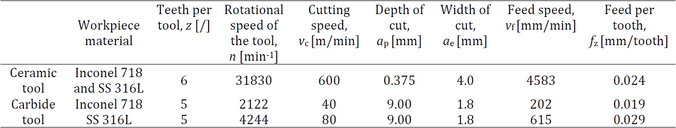
With further experiments, we came to conclusion that tools failed due to mechanical overload in radial direction because of too big depth of cut (ap = 4.5 mm) and small width of cut (ae = 0.6 mm). To change the direction of mechanical loads, from radial to axial direction, milling strategy was changed. Depth of cut was reduced and width of cut was increased without affecting the MRR, consequently milling strategy was changed from side to face milling. New cutting parameters for ceramic tools were determined in collaboration with the tool manufacturer and are shown in the Table 2. Cutting parameters for carbide tools, also shown in Table 2, were given by the manufacturer.
2.3 Execution of experiments
Milling of nickel based alloy Inconel 718 and stainless steel 316L were performed under different cooling lubrication conditions: in a dry, with minimal quantity lubrication (MQL), and with a blast of air in the case of ceramic tools and, in the case of carbide tools, flooding with emulsion.
The third scenario represents the reference scenario for both.
As a machining strategy on a high speed machining center Sodick MC 430 L, spiral strategy towards the center of the workpiece (Fig. 2) was chosen. Thus, continuous machining without interruptions and consequentially with less temperature fluctuations, which can result in tool damage, has been assured. The machining surface of workpiece rod was top end surface, which was clamped as shown in Fig. 2. One spiral milling from the outer diameter to the center of the round represents one level. After every level of removed material, the wear of the cutting tool was measured. The measurement were executed on 3D measuring device Alicona InfiniteFocus SL, where flank wear values were determined reaching the criteria VB = 0.3 mm or VBmax = 0.6mm. Thus, tool life was obtained. Moreover, workpiece surface was analyzed over energy dispersive X‐ray spectroscopy (EDX) using the scanning electron microscope (SEM) Jeol JSM 5610. Chips were also analyzed. In addition, to get justification of the process from financial point of view, cost analysis was carried out.
%2C%20shrink%E2%80%90fit%20ceramic%20tool%20clamping%20(middle)%2C%20spiral%20milling%20strategy%20(right).jpg)
The third scenario represents the reference scenario for both.
As a machining strategy on a high speed machining center Sodick MC 430 L, spiral strategy towards the center of the workpiece (Fig. 2) was chosen. Thus, continuous machining without interruptions and consequentially with less temperature fluctuations, which can result in tool damage, has been assured. The machining surface of workpiece rod was top end surface, which was clamped as shown in Fig. 2. One spiral milling from the outer diameter to the center of the round represents one level. After every level of removed material, the wear of the cutting tool was measured. The measurement were executed on 3D measuring device Alicona InfiniteFocus SL, where flank wear values were determined reaching the criteria VB = 0.3 mm or VBmax = 0.6mm. Thus, tool life was obtained. Moreover, workpiece surface was analyzed over energy dispersive X‐ray spectroscopy (EDX) using the scanning electron microscope (SEM) Jeol JSM 5610. Chips were also analyzed. In addition, to get justification of the process from financial point of view, cost analysis was carried out.
Fig. 2 Workpiece clamping (left), shrink‐fit ceramic tool clamping (middle), spiral milling strategy (right)
3. Results and discussion
3.1 Tool life and tool wear mechanisms
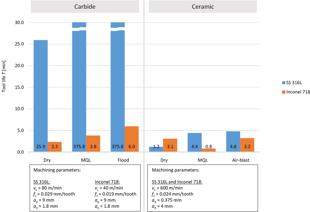
During the experiments, the flank wear of end milling tools were measured with 3D measuring device Alicona InfiniteFocusSL. Tool life shown in Fig. 3 was recorder when the flank wear of the tools reached VB = 0.3 mm or VBmax = 0.6 mm. However, this requirement was not always reached. In case fracture of the cutting tool/edge has been observed, this has also been treated as end of the tool life.
In the experiments, where carbide tools were used for machining SS 316L, cooling and lubrication conditions had major influence on the tool life. Tool life in dry machining was only 25.9 min, while in MQL and flood conditions tool life was prolonged to more than 375 min (for both conditions equally). In all of the experiments, no significant flank wear could be noticed. Before the cutting edge breakage, no flank wear was noticed, minor damages of cutting edge occurred, i.e. chipping (Fig. 4). Tool life of carbide tools, when machining Inconel 718, was significantly shorter in comparison to those used for machining SS 316L. Due to strain hardening of Inconel 718, breakage of the cutting edge is the main reason for tool failure. Best result of 6.0 min was achieved when flooding was used, while in dry the tool life reached 2.3 min and with MQL 3.8 min.
In the experiments, where ceramic tools were used for machining SS 316L, flank wear was evident. In dry conditions, the main wear mechanism was diffusion, the threshold of tool life was achieved in 1.2 min. When air‐blast and MQL were used, tool life was longer (4.8 min and 4.4 min, respectively). As the tool wear increased, the amount of BUE also increased, influencing the cutting geometry in the cutting zone. Main wear mechanism was diffusion (also confirmed in), chipping of the cutting edge was also present, unlike when machining Inconel 718, where this was the main wear mechanism (Fig 5). Because of chipping, geometry of the cutting edge changed, what resulted in chips being welded on the cutting edge (BUE). As a consequence, severe deformation of the workpiece material occurred, which resulted in even more severe material strain hardening. This normally increases forces applied to the end milling tool and loads on the cutting edge. Additionally, the flow of the workpiece material also changes, what was evident by the fact that there was much more chip side flow present. In dry condition, the tool life equals 3.1 min, when using air‐blast it was 3.2 min, and when using MQL, it was only 0.8 min (due to breakage of the cutting tooth). Thus, it can be concluded that carbide tools have significantly shorter tool life when machining nickel‐based alloy in comparison with stainless steel. This difference is not so significant when using ceramic cutting tools.
Fig. 3 Tool life achieved when milling Inconel 718 and SS 316L with ceramic and carbide tools
%20and%20carbide%20tools%20(with%20flood)%20when%20milling%20Inconel%20718.jpg)
Fig. 4 Wear mechanisms of ceramic (with air‐blast) and carbide tools (with flood) when milling Inconel 718 and SS 316L
.jpg)
Fig. 5 Wear morphology for ceramic end milling tool (when dry machining Inconel 718)
Furthermore, using scanning electron microscope (SEM) images of new and worn ceramic end milling tool were taken and analyzed, as shown in Fig. 6. On different locations of the tool, energy‐dispersive X‐ray spectroscopy (EDX) was performed to get chemical characterization or elemental analysis of specimen’s analyzed section. When new ceramic end milling tool was analyzed, EDX spectrum showed that it consists mainly of the Si, Al, O elements, which was anticipated, as this are the main elements of SiAlON ceramics. When worn out ceramic end milling tool was analyzed, EDX analysis was performed on 3 different sections of the specimen. As it can be seen from the Fig. 6, the first section with label 1, contains Cr, Ni, Fe and other elements that fit into the chemical composition of Inconel 718 alloy. This means that workpiece material was smeared over the tool surface (also shown in Fig. 5). Under this layer of workpiece material, diffusion is taking place. This layer has different thermal expansion coefficient as material of the tool, what means that during temperature fluctuations tool expands differently as main material.
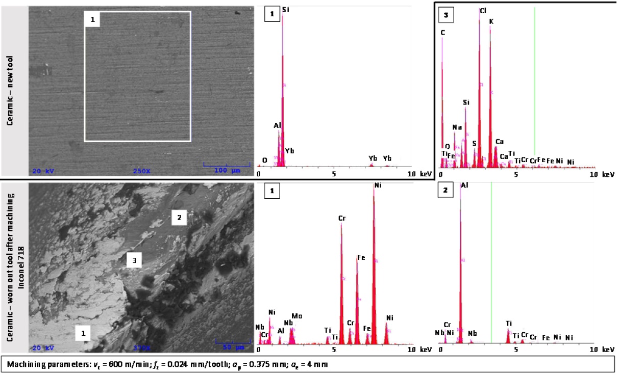
Fig. 6 SEM‐EDX analysis of ceramic tool; new tool and worn out tool after machining Inconel 718
This result in the occurrence of micro cracks on the cutting tool and its edges. Spectrum analysis of section 2 in Fig. 6 showed that this is the area of the tool where the surface of the tool already chipped away during milling and consists out of elements that are found in used ceramic material. Section 3 consists of C, CL, K and other elements which are not main components neither of workpiece or tool material. Darker spots in Fig. 6 are impurities that have been left on the tool after the machining process, during the transportation and handling with the specimen.
Ceramic tools achieved longer tool life than carbide tools only for dry machining of Inconel 718. Based on tool life alone, it seems that ceramic performance was lower than that of the carbide tools. However, ceramic tools used in this research have optimized geometry for roughing and therefore, are not suitable for finishing applications. Therefore, volume of removed work‐ piece material (productivity) was taken into consideration.
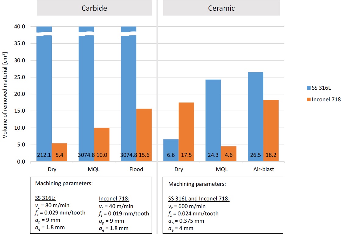
Fig. 7 Volume of removed material when milling Inconel 718 and SS 316L with ceramic and carbide tools
Fig. 7 shows volume of removed material that each tool removes in its lifetime. In all the experiments, where SS 316L was used, carbide tools outperformed ceramic end milling tools. On the contrary, when machining Inconel 718, ceramic tools in two experiments (out of six) removed more material then carbide tools. Ceramic tools in dry machining of Inconel 718 removed 17.5 cm3 and 18.2 cm3 when air‐blast was used. The highest amount removed with carbide tools was 15.6 cm3, in flood cooling lubrication conditions. The results show that ceramic end milling tools are capable of removing more workpiece material, regardless of their shorter lifetime. This is possible due to their much higher material removal rate.
3.2 Workpiece surface analysis
Fig. 8 is showing SEM and EDX images/results of SS 316L before and after machining, where two different structures were found. EDX spectroscopy showed that structure with label 1 is small ceramic particle, part of the tool, which chipped away during machining. Other darker structures (with label 2) are made primarily from carbon, what indicates some organic dirt/impurities.
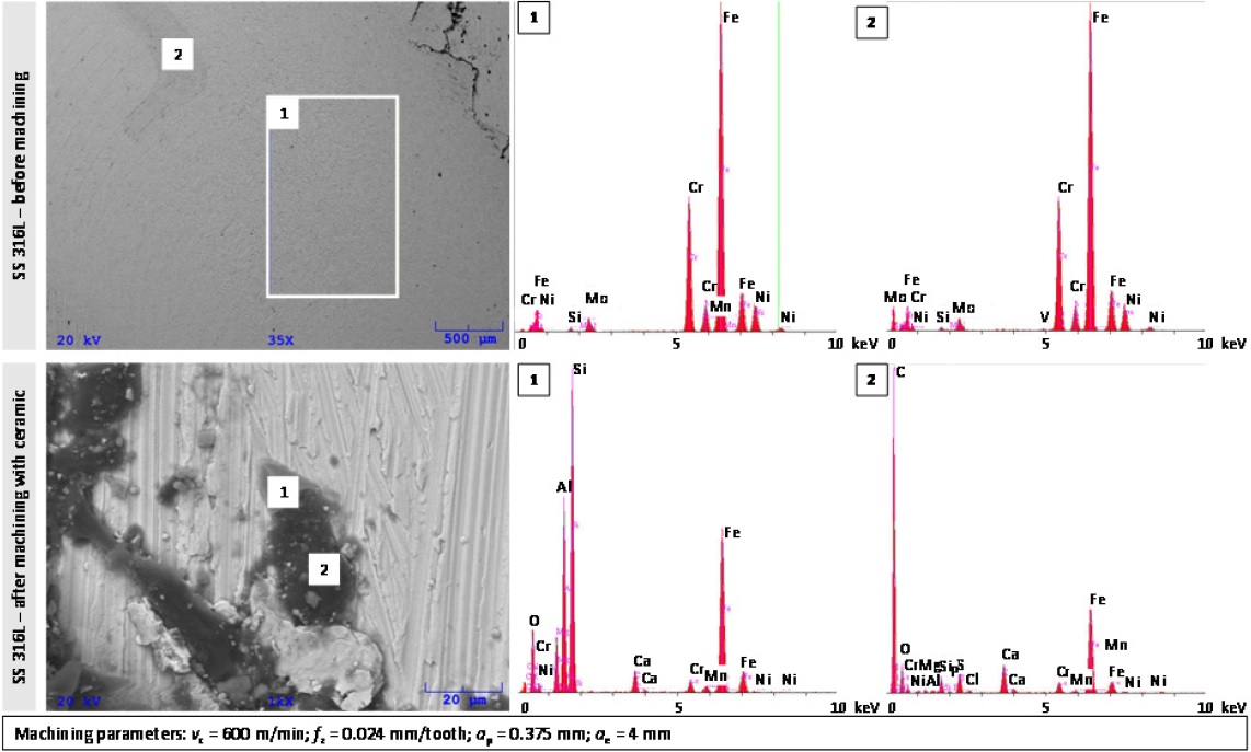
Fig. 8 SEM‐EDX analysis of SS 316L; before and after machining with ceramic tool
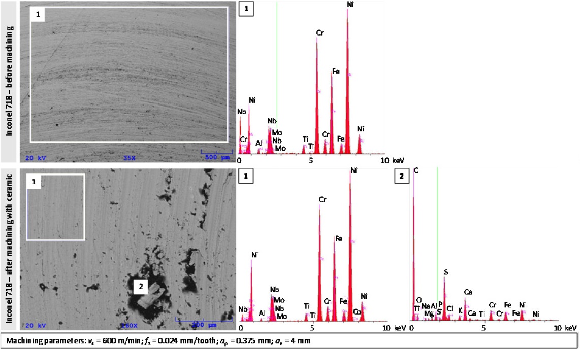
Fig. 9 SEM‐EDX analysis of Inconel 718; before and after machining with ceramic tool
These two structures (small ceramic structures and dirt) can only be found on the parts of the machined workpiece surface where the material side‐flow appeared during machining process. EDX analysis of Inconel 718 workpiece (Fig. 9), before and after machining, showed that in machined surface many imperfections can be found. In these recesses, different dirt/impurities are stuck which mainly consists out of carbon.
3.3 Chip shapes
During the milling experiments, chips were collected for further analysis and comparison. The chips formed at different experiments are shown in Fig. 10. In all the experiments, where workpiece (SS 316L and/or Inconel 718) was machined with carbide tools, either with a new or worn out tool, no major differences in chip thickness, width and all in all appearance was noticed. Their length was 9.00 mm, width 0.54 mm and their thickness was 0.096 mm. The only difference that can be observed between chips are some scratch marks on the chips produced while machining with worn tool. After further analysis, it was seen that the tool’s cutting edge was damaged, via noticed chipping of the cutting edge.
In experiments, where ceramic end milling tools were used, the cutting speed was much higher than for carbide tools. Consequentially, temperature in the cutting zone was also higher. This plays an important role in cutting performance. If the temperature in the cutting zone is lower than softening temperature of the work material, then it is easier for this material to strain harden. Therefore, beneficial in those machining application is to reach the cutting temperature that is higher than critical temperature, reducing the cutting forces and prolonging the tool life. The observations from this are consistent with results presented in. With other words, cutting temperature plays a very important role in cutting of Inconel 718 and, at the same time, it influences the chip formation. In experiments, where ceramic end milling tools were used, chips were small, in shape of dust and small particles, regardless of workpiece material machined. With the progression of tool wear, chips were getting smaller and a few elementary curled swirl chips occurred. During milling, these chips were formed from side flow material.
From the cooling lubrication point of view, regardless of the strategy that was used in both cases, when carbide or ceramic tools were used, there was no significant difference in form of chips (dry, air‐blast, MQL or flood) observed.
.jpg)
In experiments, where ceramic end milling tools were used, the cutting speed was much higher than for carbide tools. Consequentially, temperature in the cutting zone was also higher. This plays an important role in cutting performance. If the temperature in the cutting zone is lower than softening temperature of the work material, then it is easier for this material to strain harden. Therefore, beneficial in those machining application is to reach the cutting temperature that is higher than critical temperature, reducing the cutting forces and prolonging the tool life. The observations from this are consistent with results presented in. With other words, cutting temperature plays a very important role in cutting of Inconel 718 and, at the same time, it influences the chip formation. In experiments, where ceramic end milling tools were used, chips were small, in shape of dust and small particles, regardless of workpiece material machined. With the progression of tool wear, chips were getting smaller and a few elementary curled swirl chips occurred. During milling, these chips were formed from side flow material.
From the cooling lubrication point of view, regardless of the strategy that was used in both cases, when carbide or ceramic tools were used, there was no significant difference in form of chips (dry, air‐blast, MQL or flood) observed.
Fig. 10 Chip shapes formed when milling SS 316L with ceramic and carbide tools (dry conditions)
3.4 Cost analysis
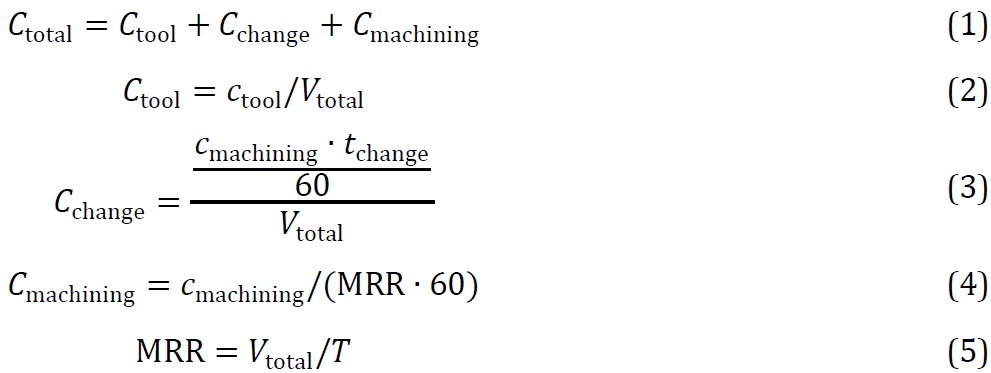
Selection of tools in industrial applications is not only performed based on tools’ performance, but also on its costs. In this research, total manufacturing cost for using ceramic or carbide tools were calculated. Ctotal is defined by Eq. 1, where Ctool is the total tooling cost, Cchange is the total cost of tool changes, and Cmachining is the cost of machining time required. All three costs are normalized in the way that present expenses required to remove 1 cm3 of workpiece material. In this way, the productivity (MRR), as well as costs, can be compared between different tool performances. With this omitted is the problem with presenting results in relation to different MRR values of processes. Ctool can be written as Eq. 2, where Ctool is the cost of the tool and Vtotal is the volume of removed material with single tool. For calculations, cost of 93 € per ceramic tool and 44.2 € per carbide tool were considered. Cchange can be calculated using Eq. 3, where Cmachining is the cost of machining per unit time, including machining labour cost, i.e. 40 €/h and tchange that represents the time to change a single tool (that includes a collection of non‐machining time, set to 5 min). Cmachining can be calculate by Eq. 4, where MRR is material removal rate given by Eq. 5, where T presents the tool life.
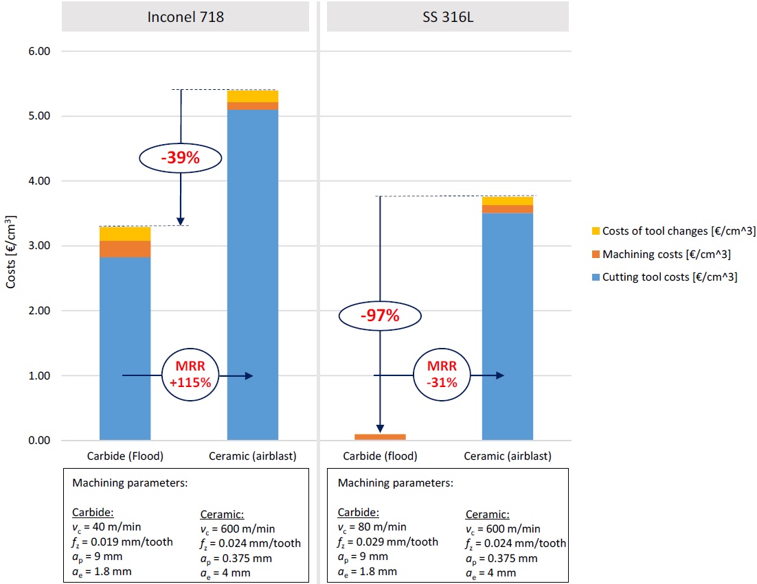
Cost analyses were performed and compared for experiments where longest tool life have been achieved. Results presented in Fig. 11 are showing that regardless of workpiece material, ceramic tools are more expensive than carbide tools. In experiments, where carbide tools were used for machining SS 316L (in flood conditions), the main expenses were machining costs. Tool costs and tool changing costs were insignificant due to long tool life. On the contrary, in other three experiments, tool life results were significantly shorter, which reflected in tool costs as the main expense. Regarding productivity, ceramic milling tools are offering 115 % higher MRR than carbide tools only when machining Inconel 718. However, there are still 39 % higher overall expenses of ceramics over carbide tools, as saved time due to higher productivity has less impact on total machining costs than purchase price of the tool.
Cost analyses were performed and compared for experiments where longest tool life have been achieved. Results presented in Fig. 11 are showing that regardless of workpiece material, ceramic tools are more expensive than carbide tools. In experiments, where carbide tools were used for machining SS 316L (in flood conditions), the main expenses were machining costs. Tool costs and tool changing costs were insignificant due to long tool life. On the contrary, in other three experiments, tool life results were significantly shorter, which reflected in tool costs as the main expense. Regarding productivity, ceramic milling tools are offering 115 % higher MRR than carbide tools only when machining Inconel 718. However, there are still 39 % higher overall expenses of ceramics over carbide tools, as saved time due to higher productivity has less impact on total machining costs than purchase price of the tool.
Fig. 11 Cost analysis when milling Inconel 718 and SS 316L with ceramic and carbide tools
4. Conclusion
This research comparatively investigates the cutting performance of solid ceramic end milling tools in machining of nickel based alloy Inconel 718 and austenitic stainless steel 316L, under different cooling lubrication conditions. Main objective was to determine machining performance of solid ceramic end milling tools in comparison with solid carbide tools, as most of the studies were done using interchangeable cutting inserts. Tool wear, tool life, workpiece surface and chip shapes and machining costs were analyzed. From the results concluded can be that:
• Ceramic end milling tools have the longest tool life in dry milling conditions, i.e. 3.1 min (dry) or 3.2 min (air-blast). In addition, air blasting can improve chip evacuation and therefore, can prolong tool life of the ceramic tools. Furthermore, carbide tools should be used only in wet cooling and lubrication conditions (flooding with emulsion).
• Main tool wear mechanism, using ceramic tools, is chipping of the cutting edge. This wear is especially pronounced when using MQL, which indicates that ceramic tools are prone to brittle fracturing when they are exposed to fast temperature changes.
• Carbide tools with appropriate cooling and lubrication outperforms ceramic tools when machining SS 316L. It can be seen, that carbide tools in comparison with ceramic tools, had longer tool life and removed more material, which resulted also in a lower overall costs.
• Ceramic tools provide better cutting performance in comparison with carbide tools only when machining of nickel based alloy Inconel 718 is performed dry. Moreover, ceramic end milling tools, which are offering higher MRR, removed more material in lifetime (18.2 cm3) than carbide tools (15.6 cm3). However, it is still questionable, if these differences are sufficient to cover the 39 % higher overall expenses of ceramics over carbide tools.