Detecting Milling Deformation in 7075 Aluminum Alloy Aeronautical Monolithic Components Using the Quasi-Symmetric Machining Method
2020-05-05
Abstract
The deformation of aeronautical monolithic components due to CNC machining is a bottle-neck issue in the aviation industry. The residual stress releases and redistributes in the process of material removal, and the distortion of the monolithic component is generated. The traditional one-side machining method will produce oversize deformation. Based on the three-stage CNC machining method, the quasi-symmetric machining method is developed in this study to reduce deformation by symmetry material removal using the M-symmetry distribution law of residual stress. The mechanism of milling deformation due to residual stress is investigated. A deformation experiment was conducted using traditional one-side machining method and quasi-symmetric machining method to compare with finite element method (FEM). The deformation parameters are validated by comparative results. Most of the errors are within 10%. The reason for these errors is determined to improve the reliability of the method. Moreover, the maximum deformation value of using quasi-symmetric machining method is within 20% of that of using the traditional one-side machining method. This result shows the quasi-symmetric machining method is effective in reducing deformation caused by residual stress. Thus, this research introduces an effective method for reducing the deformation of monolithic thin-walled components in the CNC milling process.
1. Introduction
Whole aeronautic thin-walled structures produced by various methods are widely used in aerospace technology, especially produced by machining methods. Schubert et al. posed that the light-weight components are of crucial interest for all branches that produce moving masses. The aim to reduce weight has to be accompanied by high production efficiency and component performance. Mangalgiri proposed that the complicated materials and composite materials would been used extensively.
However, when oversize whole aeronautic structure is machined, most of material is removed causing its deformation, which is thought to be a hard work universally in the aerospace manufacturing field. Dong and Ke summarized that the main cause of deformation is that when a large amount of material is removed, the residual stress equilibrium in the blank is broken. To re-equilibrate it, the residual stress is redistributed, and the distortion of the monolithic component is generated at the same time. At the same time, Wang et al. made a similar point that when machining thin-walled aeroplane parts, more than 90% of the material would be removed, resulting in severe distortion of the parts due to the weakened rigidity and the release of residual stress. This might also lead to stress concentration and damage of the parts. Thus, the residual stress is one of the most important reasons for machining deformation of aeronautic thin-walled structure. Meanwhile, a great number of workpieces are manufactured by high-speed milling, where problems can arise related to chatter vibration, an instable process. Chatter phenomena appear in the high removal rate roughing, as well as in the finishing of low-rigidity airframe components.
A number of studies have focused on the influence of different machining process of thin-walled plates to aid in the optimization of mechanical manufacturing processes. Guo et al. established a three-dimensional (3-D) finite element model with consideration of an initial residual stress field to compute the machining deformation of thin-walled frame shape workpiece. Jomaa et al. presented an experimental study of the surface finish and residual stress induced by the orthogonal dry machining of AA7075-T651 alloys and investigated the surface damage mechanisms in detail. Liu posed the 3-D finite element models of a helical tool and a thin-walled part with a cantilever to predict the cutting deformation of a Ti6Al4V titanium alloy thin-walled part in milling process.
Using a Lagrangian formulation with an explicit solution scheme and a penalty contact algorithm, Maurel-Pantel et al. investigated the simulations of shoulder milling operations on AISI 304L stainless steel using the commercial software LS-Dyna. Eslampanah et al. employed the thermal elastic-plastic finite element method to predict residual stress and deformation in a T-Fillet welded joint, and developed an uncoupled thermal-mechanical 3-D model. Ocana et al. presented a model to provide a predictive estimation of the residual stress and surface deformation induced by laser action relevant for analysis the influence of different parameters in the milling process.
In order to increase productivity and tool life in machining of titanium alloys, Nouari and Makich studied the poor machinability of titanium alloys, especially Ti-55531, which exhibits extreme tool wear and unstable cutting forces. Denkena et al. presented an approach for the identification and modeling of these process damping effects in transient milling simulations, and a simulation- and experiment-based procedure for the identification of required simulation parameters depending on the tool chamfer geometry is introduced and evaluated. Abe and Sasahara explored the relationship between residual stress and temperature distribution in the shell structure after lamination and measured the deformation caused by residual stress release. This article focuses on reducing deformation caused by residual stress during the milling process.
Other studies concentrated on the different research method for analysis the relationship between deformation and residual stress, especially the computer simulation and experimental study method. Wei and Wang established a finite element model of original residual stress to analyze the corresponding deflection by machining aerospace thin-walled parts, especially in machining large aerospace parts, and simulation results were validated approximately consistent with experimental results.
Yaghi et al. discussed the residual stress in thin- and thick-walled stainless steel pipe-welded components and presented a brief review of weld simulation, and analyzed more FE models with an inside radius to wall thickness ratio to investigate the effect of pipe diameter on residual stress. Wu and Li proposed a numerical approach to predict the surface residual stress and strain gradients resulting from a 3D milling process. The finite element simulation of residual stresses is compared with experiments based on X-ray measurements on 7075 samples machined under different cutting conditions. The effects of cutting conditions on surface residual stress distribution are investigated.
Husson et al. presented an approach to estimate the influence of some factors on the distortion, based on the idea of a distortion potential taking into account not only geometry but also the residual stress. To study the effect of blank initial residual stress on component deformation, Huang et al. used chemical milling to remove the machining-induced residual stress on the machined surface of the components and proved that the initial residual stress in the blank was the main factor of deformation for a three-frame monolithic beam.
Taking into account the deformation of thin-walled parts being significantly affected by the residual stress generated after the material is cut away, Li et al. analyzed the effects of cutting depth on the redistribution of residual stress and demonstrated that the magnitude of distortion and residual stress can be decreased and optimized efficiently by controlling and optimizing the depth of cut in the roughing and finishing. The current paper presents the quasi-symmetric machining method and FEM to reduce deformation caused by residual stress.
Some researchers concentrated on finding the approaches for analyzing and controlling residual stress. Muñoz-Sánchez et al. developed and validated a numerical model to analyze the tool wear effect in machining induced residual stresses. The model was applied to predict machining induced residual stresses in AISI 316 L. Ballestra et al. studied the dynamic characterization of gold micro beams by electrostatic excitation in the presence of residual stress gradient, experimentally. Additionally, a comparison with different numerical FEM models and experimental results has been carried out.
Chen et al. investigated the effect of electrical contact on the thermal contact stress of a microrelay switch. The results showed that the residual stress increased as the number of switching cycles increased. Based on the uncut chip thickness (UCT) model, Jiang et al. found that residual tangential stress is influenced by the UCT and it is possible to optimize the residual stress distribution by controlling UCT (feed rate and tool diameter) with high-speed milling, and in order to control the material removal rate, they proposed a method by optimizing the milling tool diameters based on the relation between residual stress and UCT. Zhang et al. provided some insight into the uniformity of compressive residual stress generated by massive overlapping laser shock peening impacts, which has a lot of practical use in engineering application.
Mohammadpour et al. conducted a finite element analysis based on the nonlinear finite element code MSC. Superform for investigating the effect of cutting speed and feed rate on surface and subsurface residual stress induced after orthogonal cutting. Toribio et al. dealt with the effect of several residual stress profiles on the fatigue crack propagation in pre-stressing steel wires subjected to tension loading or bending moments. Considering the cutter radius of the milling process, Li et al. created a model to analyze cutting force and thermal properties in the high-speed milling process and, combined with experimental validation, indicate that mechanical forces play an essential part on the formation of residual stress.
Palkowski et al. presented a 3-D model to calculate the residual stress state of drawn tubes in cold drawing processing. Krottenthaler presented a simple method to determine residual stress of thin films, locally, by using stress relaxation tests by means of focused ion beam (FIB) milling and digital image correlation (DIC) and the proposed method offered a simple way for analyzing residual stresses in thin amorphous coatings. Additionally, nanohardness of the thin films was measured by nanoindentation, and residual stress was determined using grazing incidence X-ray diffraction.
However, the traditional one-side machining method will produce oversized deformation caused by residual stress. The current paper presents the quasi-symmetric machining method to reduce deformation by symmetrical material removal using the M-symmetry distribution law of residual stress. The obtained results are compared with those of FEM. The quasi-symmetric machining method is validated as a reliable and effective method in reducing deformation caused by residual stress.
2. Analyses of Deformation Caused by Residual Stress Releasing
The initial residual stress in pre-stretched 7075aluminum alloy plate, produced in the process of rolling, heat-treatment, and stretching, need to meet the universal hypothesis. The initial residual stress is a self-balanced force, and the resultant force and resultant moment in the cross-section that is perpendicular to the stress are zero; that is:
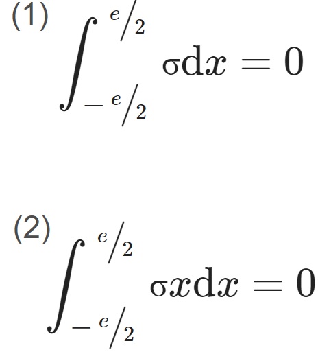
where e is the thickness of the thin-walled plate, and σ is the initial residual stress of the thin-walled plate.
Residual stress of each layer that is segmented, on average, along the thickness direction and is showed in the Figure 1. The thickness of each layer is t, and the average residual stress of each layer is. σ1, σ2,………,σn.
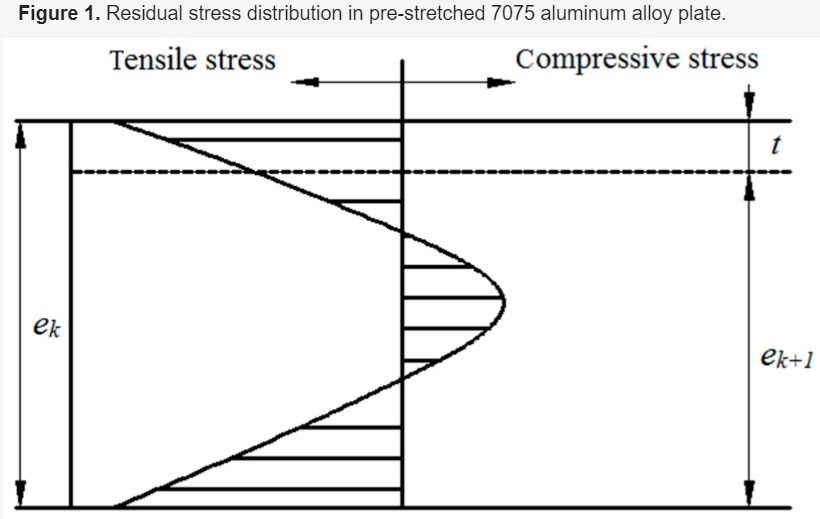
Figure 1. Residual stress distribution in pre-stretched 7075 aluminum alloy plate.
When materials are removed in milling, the initial residual stress equilibration is broken. To re-equilibrate it, the residual stress is redistributed, and the distortion of the plate is generated at the same time. The curvature relation of the workpiece before and after milling a layer is as follows:
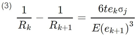
Where k is the number of the layer, Rk and Rk+1 are the curvature radius before and after the kth layer is stripped, ek and ek+1 are the thickness of workpiece before and after the kth layer is stripped, σj is the stress before the kth layer is stripped, and E is the elastic modulus.
In this equation, j = k − 1 (when k = 1, σj = σ1). When k = 1, σj represents the initial stress.
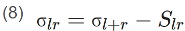
The remaining stress σkr in each layer after the kth layer being stripped is obtained by vector operations between the stress σim before the kth layer being stripped and the generated stress Ski. The computational process is:
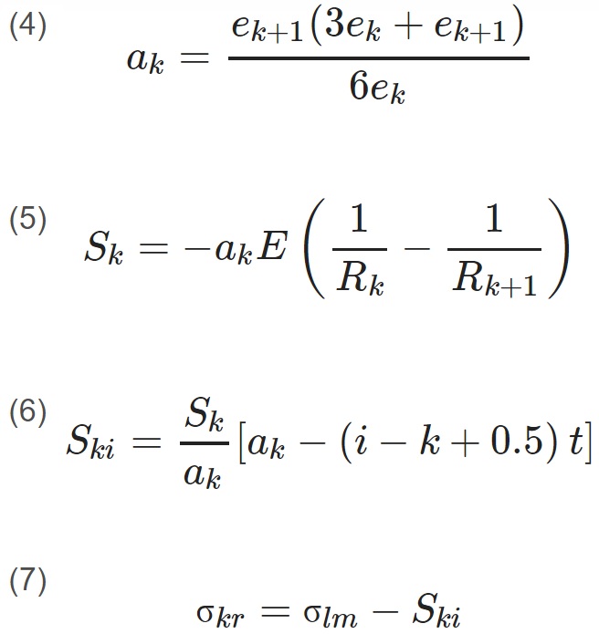
Where l = k − 1, m = r + 1, i = r + k − 1, r = 1,2,… n − k, k ≥ 2.
When k = 1, then:
After the kth layer is stripped, ak and bk are the distance from upper surface and lower surface to the neutral plane, respectively. Sk and Sk’ are the stress generated on the upper surface and lower surface when the rest of workpiece recovers to the shape before the kth layer being stripped, respectively. This is shown in Figure 2.
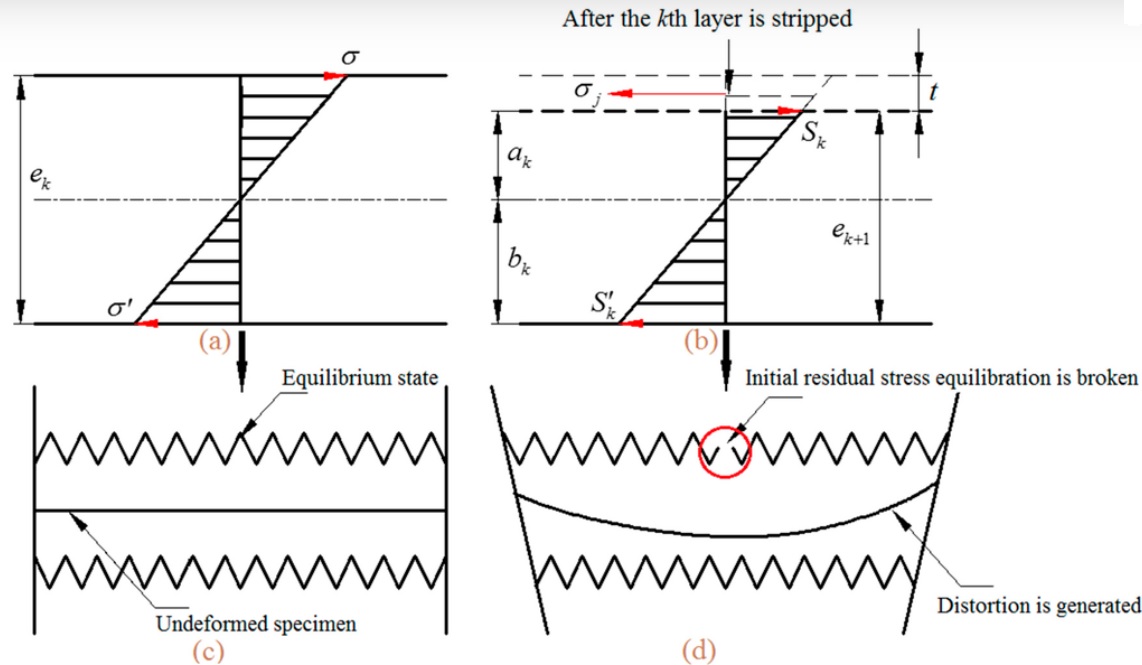
Figure 2. Stress state and deformed condition of the specimen before and after the kth layer is stripped. (a) and (c) show the equilibrium stress state and undeformed condition; (b) and (d) the re-equilibrium stress state and deformed condition.
For a more intuitive description of deformation principle, the stress state and deformation condition have been simplified, as shown in Figure 2. As depicted in Figure 2a,c, they are the equilibrium stress state and undeformed condition of the specimen before the kth layer is stripped. Moreover, the re-equilibrium stress state and deformed condition, after the kth layer is stripped, are exhibited in Figure 2b,d. The residual stress release and redistribute in the process of kth layer material removed, and the distortion of monolithic component is generated.
3. Analyses of Quasi-Symmetric Processing Technique
The sectioning technique is a destructive measurement method for material that relies on the measurement of deformation due to the release of residual stress upon removal of material from the specimen. The strains released during the cutting process are generally measured using electrical or mechanical strain gauges. As is shown in Figure 3, using the sectioning technique, the excellent residual stress measurement results are obtained, and the distribution of residual stress in pre-stretched 7075 aluminum alloy plate present M-symmetry distribution along the thickness (Figure 4). The residual stress is tensile stress at the surface and in the middle, and compressive stress in the upper and lower part, respectively. This uneven tensile or compressive stress distribution along the thickness is the major cause of subsequent deformation. After some adjustment, the initial residual stress of 7075 aluminum alloy plate only partially reduced. Nonetheless, the trend of the M-symmetric distribution law will not change any more.
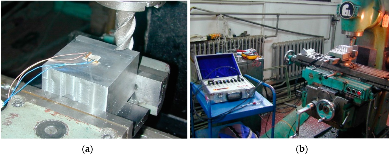
Figure 3. Quasi-nondestructive test for measuring distribution of residual stress. (a) Strain gauges and wire connecting; and (b) test equipment.
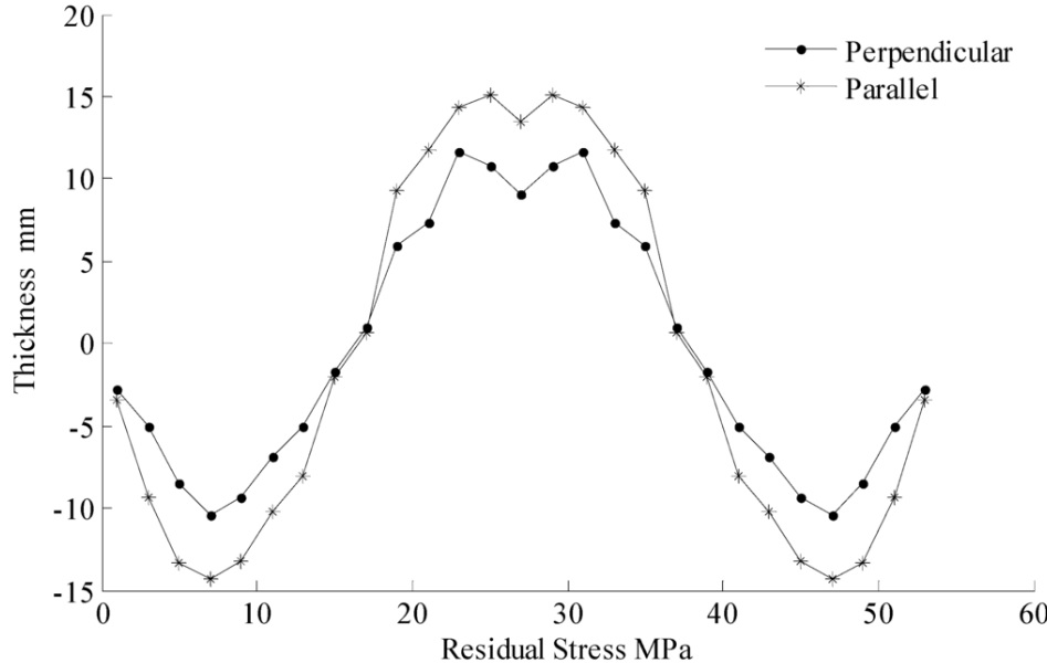
Figure 4. M-symmetric distribution law of initial residual stress.
Since the distribution of residual stress in pre-stretched 7075 aluminum alloy plate present M-symmetry distribution along the thickness, the symmetric machining method can reduce the deformation caused by the releasing and redistribution of the initial residual stress. For double-sided machining,the three-stage CNC machining method processes the upper surface to small allowances, then the lower surface to the precise size, then the allowance of the upper surface to an accurate size. Based on the three-stage CNC machining method, the quasi-symmetric machining method is developed to reduce deformation by symmetry material removal using the M-symmetry distribution law of residual stress. The plate is processed several times on both sides, repeatedly, to the accurate size.
4. Solution for the Plates Using FEM
Due to the high cutting speed and small cutting depth, the cutting force and cutting heat of pre-stretched 7075 aluminum alloy plate produced in the process of CNC machining on high-speed machine tools can be negligible. In addition, the influence of the clamping scheme for machining distortion is negligible in CNC machining processes. Therefore, this paper mainly focuses on workpiece deformation caused by releasing and redistribution of residual stress for aeronautical monolithic components in the CNC milling process.
The FEM that provides an approximate solution to continuum problems is a powerful tool to assess potential distortion caused by residual stress in the machining process. The FEM software ANSYS is applied to measure the deformation of aeronautical monolithic components in the traditional one-side machining process and quasi-symmetric machining process for further validation in this paper.
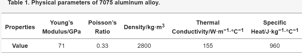
The pre-stretched 7075 aluminum alloy plate is assumed to be an elastic-plastic material. Its physical specifications are listed in Table 1, and the dimensions are 300 mm × 200 mm × 26 mm. The worktable is considered as a rigid body in the ANSYS model. In this paper, a two-sided constraint has been used for the solution in order to simulate the real fixture more authentically. Additionally, the stiffness is assumed to be infinite and displacement is assumed to be zero, respectively. Meanwhile, the influence of temperature, milling force, and clamping force are ignored.
On the basis of the M-symmetry distribution law of residual stress that was mentioned in Section 2, we assign the corresponding residual stress values into the workpiece layer by layer. Using the “birth and death element method “, we simulate the real situation of materials removed in the milling process. To achieve the “element death” effect, the ANSYS does not actually remove “killed” elements. Instead, it deactivates them by multiplying their stiffness by a severe reduction factor (10−6 by default). Then, the deformation process caused by residual stress release were simulated.
When simulate the traditional one-sided machining process, the materials of the upper surface are removed in a one-time processing. By contrast, for quasi-symmetric machining process, the materials of two surfaces are removed successively.
To facilitate description, the aeronautical monolithic component machined by the traditional one-side machining method and the quasi-symmetric machining method are labelled as Specimen 1 and 2, respectively.
Using the simulation procedure described above, the deformation distribution after the milling process are calculated by ANSYS. The model generated for this analysis is depicted in Figure 5. It can be seen from Figure 5a that the deformation trend of Specimen 1 is convex upward at both ends and concave downward at the middle, while the maximum deformation is located at the end of the specimen. On the contrary, from the Figure 5b, the deformation trend of Specimen 2 is concave downward at both ends and convex upward at the middle, while the maximum deformation is located at the middle of the specimen. As depicted in the deformation nephogram, the maximum deformation decreases by approximately 0.28 mm by the application of quasi-symmetric machining method compared to that of the traditional one-sided machining method. This result is confirmed by experimental investigation in Section 4 of this paper regarding deformation measurements.
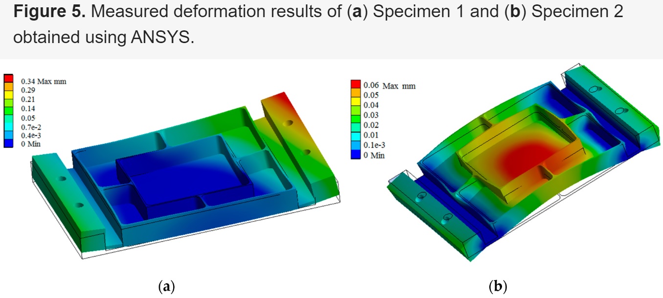
Figure 5. Measured deformation results of (a) Specimen 1 and (b) Specimen 2 obtained using ANSYS.
5. Analyses of the Experimental and Simulation Results
Consider the quantity of stiffener plate and the characteristics of the chamber profile, a reasonable simplification of an aeronautical monolithic component in view of the practical processing is made. The structure can not only reflect the real deformation, but is also in favor of the data acquisition.
In the machining process, the axial feed is 0.8 mm each time. After three passes, we removed specimens from fixture and measured the deformation. The clamping scheme of Specimen 2 in the reverse-side machining process is similar to Specimen 1, while that in the front-side machining process is shown in Figure 6.
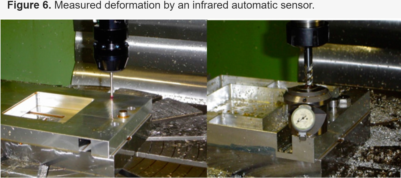
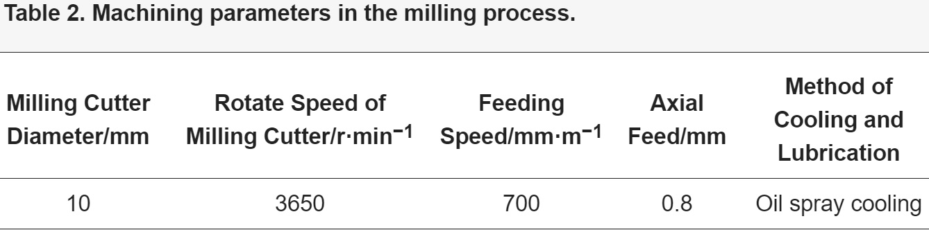
The staggered inner-milling form of the machining sequence and feed route were designed for the experiment. On a WF74CH-mikron CNC machine tool (Mikron Group, Boudry, Switzerland), a φ10 mm, four-tooth carbide milling cutter was used in the front side machining process, and a φ20 mm, two-tooth cemented carbide end milling cutter was used in the reverse side machining process. The processing parameters are shown in Table 2. Figure 6 illustrates the process of using MP8 infrared automatic sensor head to measure the specimen axial deformation.
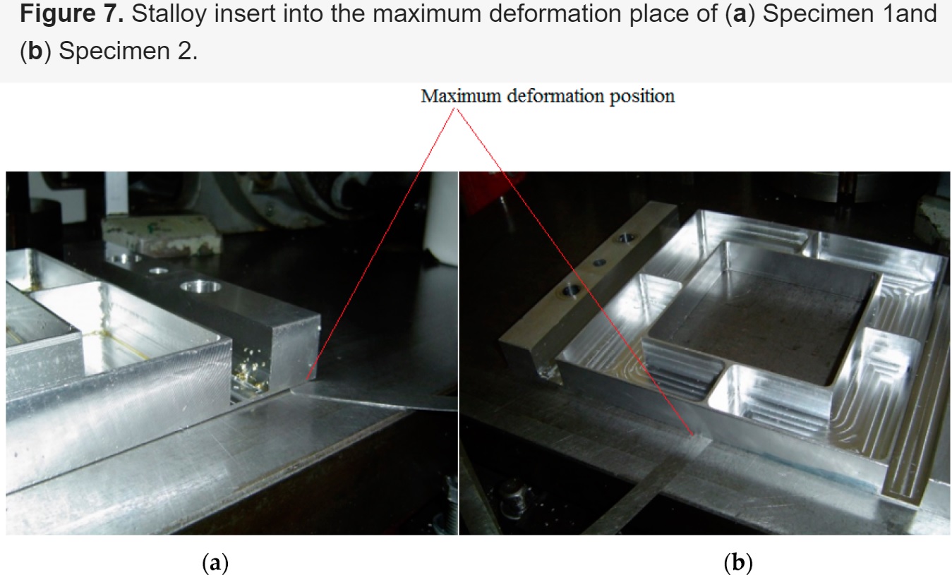
The overall deformation of Specimen 2 is smaller than that of Specimen 1, intuitively. The maximum deformation of Specimen 1 occurs at the end of the workpiece. As is shown in Figure 7a, a 0.32 mm thick stalloy insert into maximum deformation place of Specimen 1. By contrast, the maximum deformation of Specimen 2 occurs at the middle of the specimen. As is shown in Figure 7b, a 0.045 mm thick stalloy insert into maximum deformation place of Specimen 2.
The CNC machining process is a dynamic deformation process. To facilitate the description, Specimen 1 and 2 are divided into seven cross-sections along the x-coordinate, namely cross-sections A–G, and all of the seven cross-sections are perpendicular to the X-Y plane, as shown in Figure 8. The abscissa X of cross-sections A–G are 100 mm, 70 mm, 35 mm, 0 mm, −35 mm, −70 mm, −100 mm, respectively. The size and structure of the specimen are shown in the Figure 8 at the same time.
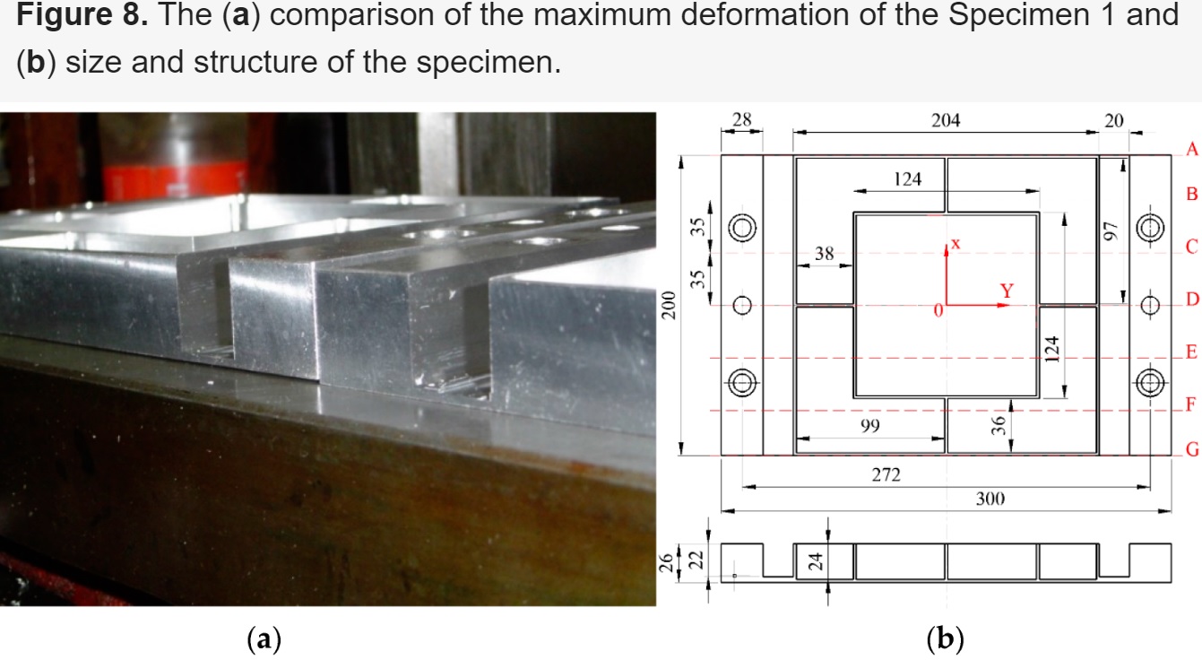
Figure 8. The (a) comparison of the maximum deformation of the Specimen 1 and (b) size and structure of the specimen.
In the milling process, the materials are removed layer by layer. Figure 9 illustrates the dynamic deformation curves of cross-sections A–G for Specimen 1 and 2 at different process stage. From Figure 9, the deformation trend and values in the process of the last six layers stripped are easily observed.
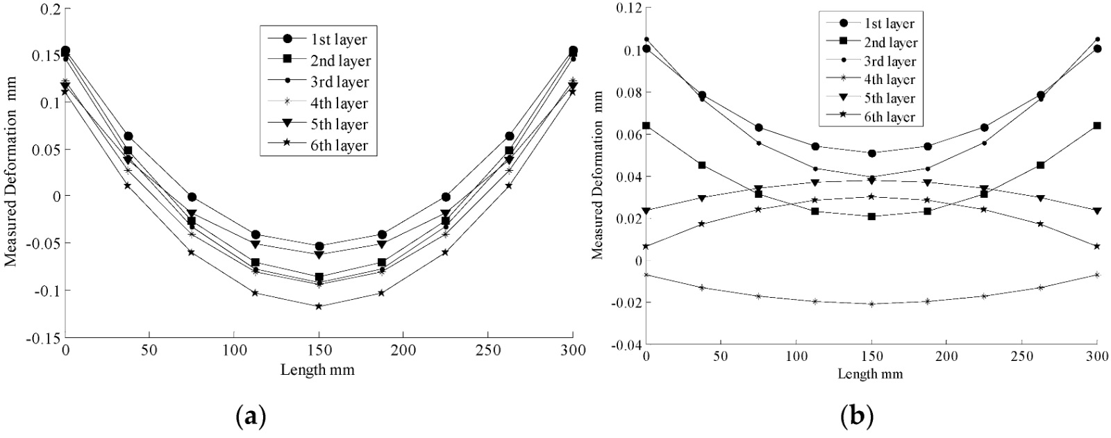
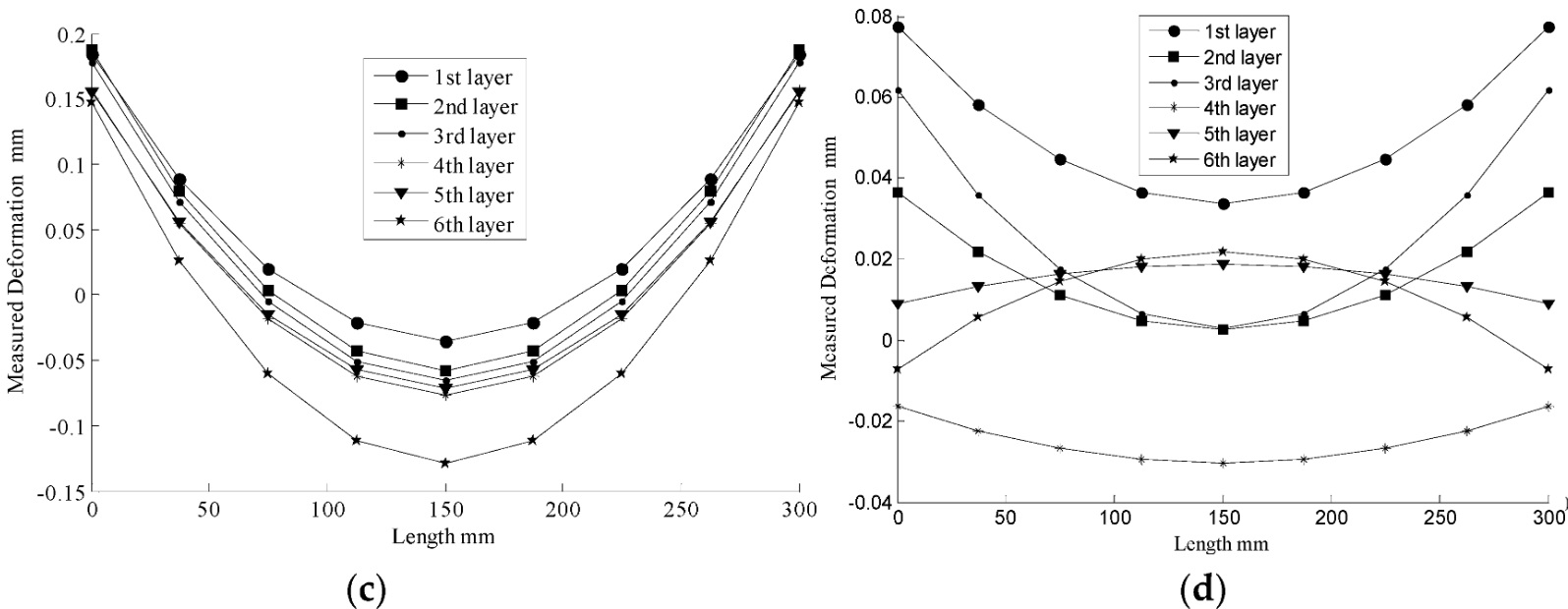
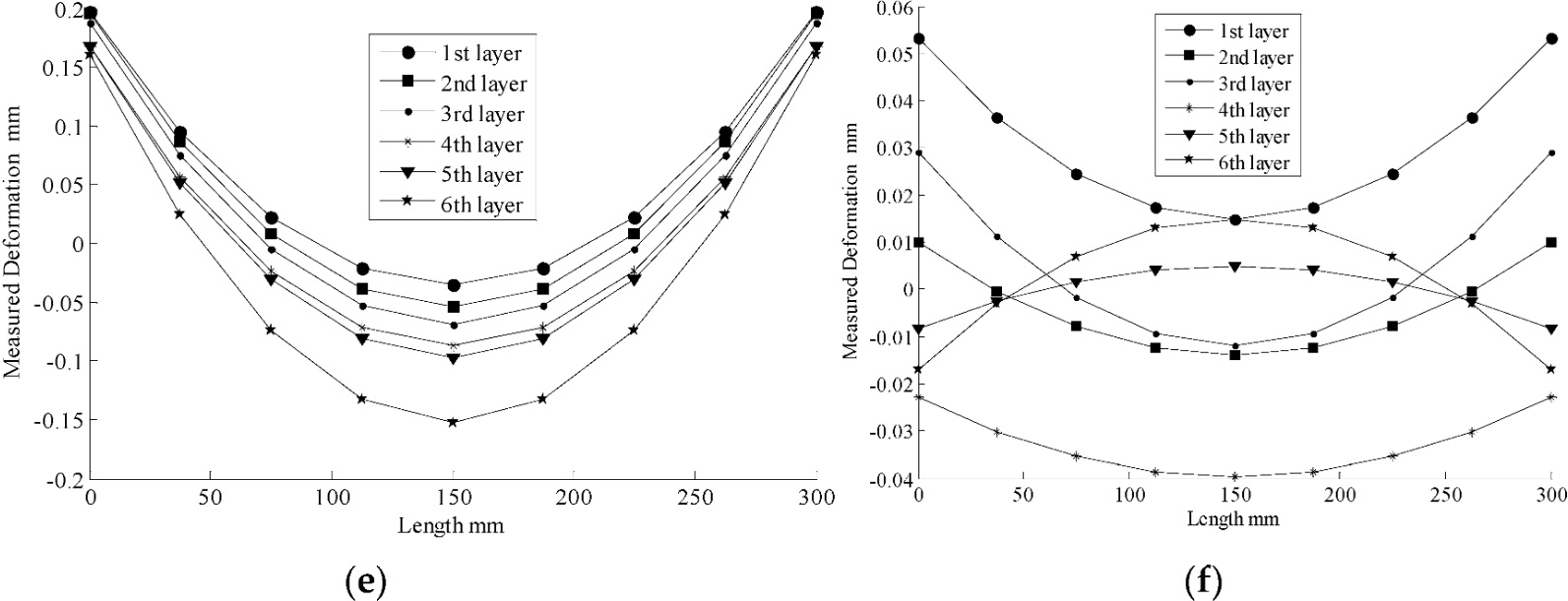
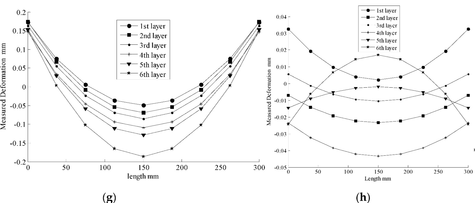
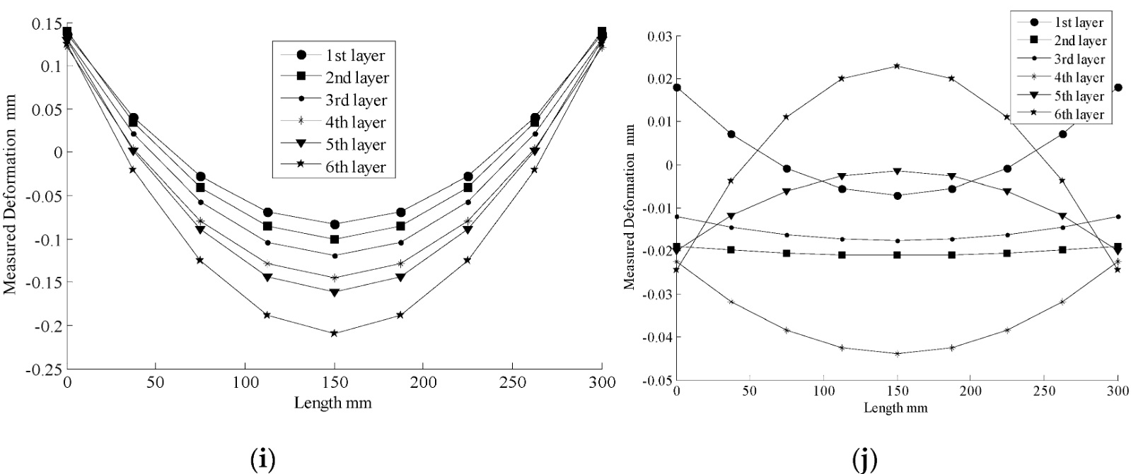
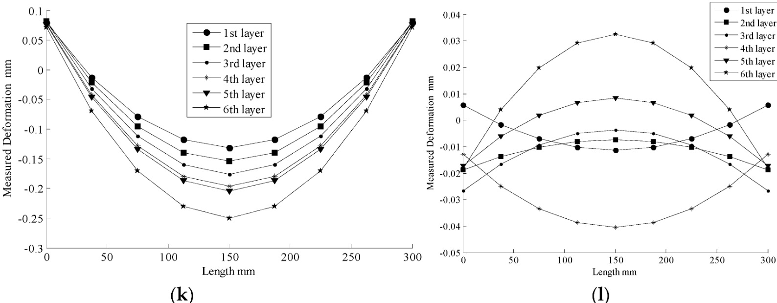
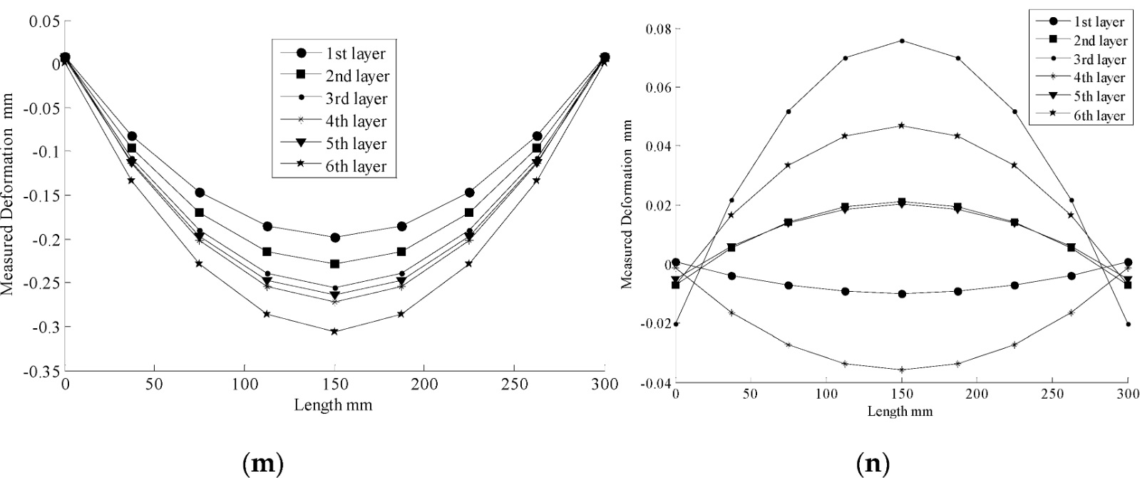
Figure 9. Deformation curves of cross-sections A-G for Specimen 1 and 2 at different process stage.
(a) Cross-section A of Specimen 1;
(b) Cross-section A of Specimen 2;
(c) Cross-section B of Specimen 1;
(d) Cross-section B of Specimen 2;
(e) Cross-section C of Specimen 1;
(f) Cross-section C of Specimen 2;
(g) Cross-section D of Specimen 1;
(h) Cross-section D of Specimen 2;
(i) Cross-section E of Specimen 1;
(j) Cross-section E of Specimen 2;
(k) Cross-section F of Specimen 1;
(l) Cross-section F of Specimen 2;
(m) Cross-section G of Specimen 1;
(n) Cross-section G of Specimen 2.
The curves of Figure 9 indicate that the deformation trend of cross-sections A–G for Specimen 1 are all convex upward at both ends and concave downward at the middle for the entirety of the machining time, while the maximum deformation occurs at the end of the specimen. Meanwhile, the deformation value increased during the materials be removed layer by layer. By contrast, the curves of Figure 9 also indicate that the deformation trend of cross-sections A–G for Specimen 2 are either concave downward at both ends and convex upward at the middle or convex upward at both ends and concave downward at the middle, which is a symmetric, repeated process. Especially, the deformation value is increased and decreased during the process, alternatively. Additionally, the maximum deformation occurs at the end of the specimen.
For the traditional one-side machining method, the residual stress releasing and redistribution happened at one side of the specimen all of the time, and the deformation caused by residual stresses were accumulated. By contrast, for the quasi-symmetric machining method, the residual stress releasing and redistribution happened on two sides of the specimen, alternatively. The deformation caused by residual stress were offset.
Meanwhile, the values of maximum deformation of cross-sections A–G for the Specimen 1 and 2 are displayed in Figure 9. The comparison of those is presented in Table 3.
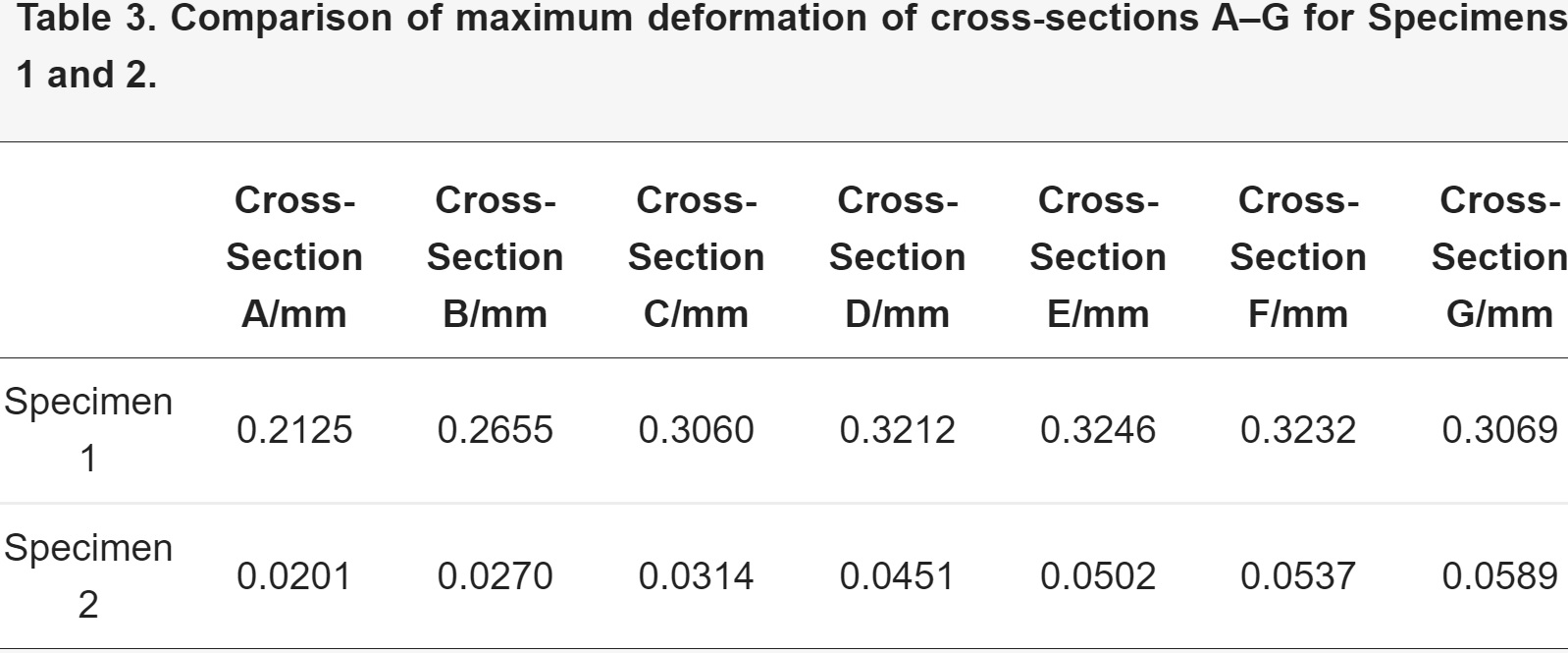
Furthermore, the maximum deformation of cross-sections A–G is compared on the basis of the results of Specimen 1 divided by those of Specimen 2, respectively. Percentages of the maximum deformation are 9.459%, 10.17%, 10.26%, 14.04%, 15.47%, 16.62%, and 19.19%, successively. Obviously, the maximum deformation of Specimen 1 is much larger than that of Specimen 2. The maximum percentage of maximum deformation is only 19.19%. Thus, the quasi-symmetric machining method is effective in reducing deformation of monolithic thin-walled components caused by residual stress.
Figure 10 illustrates the measured deformation results and deformation trend of experiment and simulation for cross-section D of an aeronautical monolithic component in the traditional one-sided machining process and the quasi-symmetric machining process. The change curves indicate the relationship between the measured deformation results of FEM and the experiment. The original data curves and quadratic fit curves presented in Figure 10 are suited, thus suggesting that the FEM results are consistent with the experimental results. These findings confirm that FEM and the experiment exhibit high accuracy in the milling process.
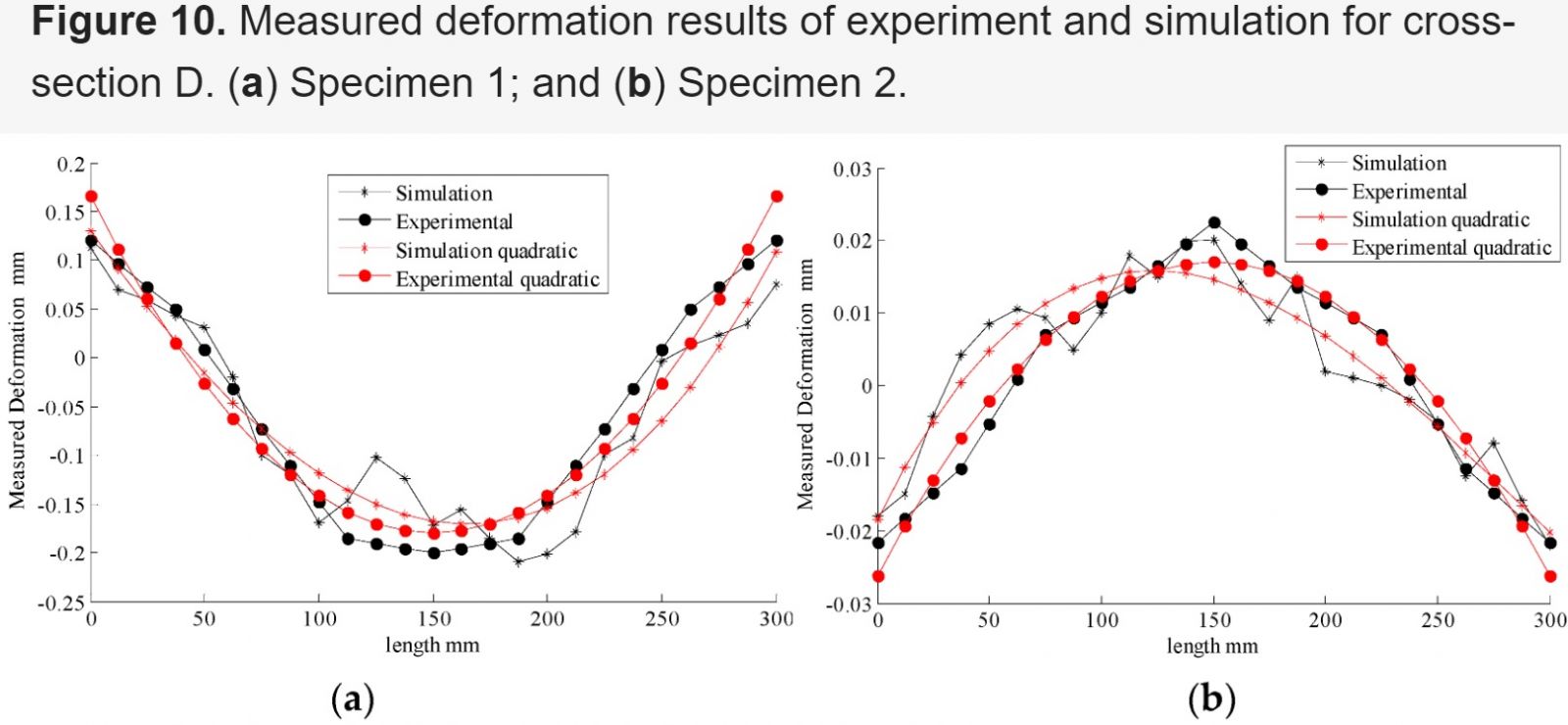
For Specimen 1, the experiment maximum deformation is 0.32 mm, while that of the simulation is 0.34 mm. By contrast, the experimental maximum deformation is 0.045 mm and the simulation maximum deformation is 0.06 mm for Specimen 2. Despite a slight deviation results comparing with the simulation and experiment, the results are very similar. Nonetheless, results of the simulation are inferior to those of the experiment, all of which remain within the allowable error. The main causes of this deviation are as follows:
1. FDM is based on the approximations that facilitate the replacement of differential equations with finite difference equations. As such, the calculation method inevitably displays systematic errors.
2. In practice, the boundary conditions are not identical in the simulation and in the experiment. The ideal condition has yet to be determined.
3. The residual stress state between simulation and experiment are not consistent. FEM simulating the true condition of residual stress releasing and redistribution, totally, is impossible. Although there are some objective reasons that lead to some certain errors, most of them are within the permitted error range.
6. Conclusions
1. The maximum deformation value of using a quasi-symmetric machining method is within 20% of that of using a traditional one-side machining method. This result shows the quasi-symmetric machining method is feasible and effective in reducing deformation of monolithic thin-walled components caused by residual stress.
2. Errors are low, and most are within 10% for modifying the comparative results of FEM and experimentation. These results confirm that the quasi-symmetric machining method is a reliable and suitable method for releasing deformation.
3. In the quasi-symmetric machining process, the deformation trend of Specimen 2 is concave downward at both ends, and convex upward at the middle, while the maximum deformation occurs at the middle of the specimen.