Durability of Cutting Tools during Machining of Very Hard and Solid Metal Materials
2020-06-14
Abstract
This paper deals with the machining of the hardened steel with carbide endmills. In the research, several different milling tools are compared in terms of their durability during machining of hardened steel. For the cutting tools different geometry, thin-film deposition or substrate of tool material, were used. The main aim is comprehensively compare all cutting tools. For the test workpiece material DIN X210Cr12 was used. Normally this material is used for producing of highly stressed molds, grinding tools or tools for cold forming. Cutting conditions are detected in the first part of the experiment, which is a short-term test according to A. S. Kondratov. Cutting conditions are used in the second part of the experiment, which is a long-term test of all tools. During the side milling of hardened steel, the flank wear is measured and durability of each tool is determined. The results of this work will be used for further research and development of cutting tools for hard machining.
1. Introduction
Hard and solid materials are very often used in the mechanical engineering industry, for example in production of cutting tools, forming tools or dies and molds. If we want to productively and competitively machine these materials, we must constantly reduce machining costs and increase the quality of machining.
Nomenclature
ae, width of cut
ap, depth of cut
Fy, further nomenclature continues down the page inside the text box
Vc, cutting speed v15 cutting speed for the durability of 15 min.
VBB, flank wear
VBkrit, critical flank wear
VBBmax, maximum flank wear reached
T, time of machining
T0.1, durability for critical flank wear 0.1 mm
TK, final time of machining
It is very important to choose the appropriate cutting tool. Optimal durability of cutting tool is one of the requirements in selecting the proper cutting tool. The cutting tool has to resist high abrasion, high pressure and temperature, during the machining of hard materials. Hard machining has its specific problems. Chip formation during machining of hardened steel for different cutting conditions was studied in. Durability and cutting power of the cutting tool is influenced by many factors, for example material of cutting tool, geometry, micro-geometry or thin-film deposition. To achieve high productivity and economic efficiency it is necessary to focus on all these factors.
Deposition of thin-film has great influence on cutting performance and it could play an important role in the final durability of the cutting tool. In, Benga et al. tested the tool life of coated and uncoated tap tools with different shapes of taps. Irrespective of the tool geometry it was obvious that cutting tools coated with TiAlN have showed longer tool life than HSS tools. The use of TiAlN has increased the tool life by 1.35 times taking into consideration the number of holes tapped. Thin-film increases surface hardness of cutting tool, decreases friction coefficient and protects cutting edge against high temperature during machining. The wear behavior as well as the performance of the cutting tool is affected by the coating. The influence of different coatings on this behavior was investigated in. The appropriate choice of thin-film is important, but the method of application of thin-film and preparation of micro-geometry of cutting edge before and after application of thin-film is also very important. Denkena et al. investigated the influence of the cutting edge preparation method on the performance of coated carbide inserts during hard machining. Combining appropriate tool material and coating has a major impact on the wear formation of the cutting tool. In paper, Aslan used different cutting tools for end milling of X210 Cr12 cold-work tool steel with hardness 62 HRC. Aslan investigated performance and wear behavior of tungsten carbide tools with different coatings, cermet, ceramic and CBN tools.
During machining of hard materials, it is necessary to use the right cutting conditions taking into account the specific properties of hard materials. Cutting conditions should also exploit the potential of the cutting tool. Due to development of cutting tools, HSC technology has also been applied in machining hardened steel for molds and dies. Research shows high-speed face milling of hardened steel AISI H13 with coated carbide tools with different cutting speeds and milling strategies. Cutting performance of CBN tools and PVD-coated carbide tools was investigated in for low speed and high speed machining strategies of hardened steel. Researchers observed the flank wear in up and down milling strategies. Cutting conditions can influence the efficiency of material removal and quality of the machined surface. Quality of the surface could be a crucial requirement which must not be overlooked. A cutting tool which is able to achieve high durability but is not able to achieve desired surface quality is uneconomical and therefore unproductive. Research shows a special carbide tool designed for face milling of AISI D3 hardened steel and its influence on surface quality.
In this paper, several monolithic carbide endmills are compared in terms of their durability during machining of DIN X210Cr12 hardened steel with hardness 62±2 HRC. For the cutting tools with different geometry, thin-film deposition or substrate of tool material were used. The main aim is comprehensive comparison of all the cutting tools and determining their durability. The results of this work will be used for further research and development of cutting tools for hard machining.
2. Experiment
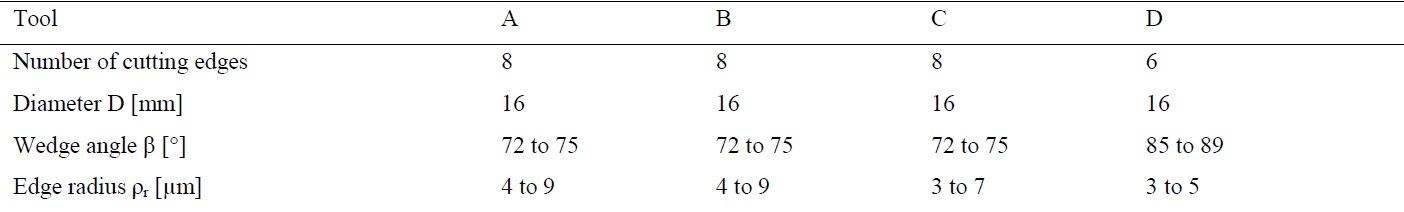
The main aim of the experiment is to determine durability of four carbide endmills. The experiment is divided into two parts. In the first part of the experiment, cutting conditions are detected and they are used it in the second part of the experiment, which is the long-term test of all tools. The flank wear is measured at intervals during machining of hardened steel until the wear reaches the critical value. Durability of each cutting tool is determined from obtained values. Four carbide endmills were used for side milling of DIN X210Cr12 hardened steel. All cutting tools are shown in Fig. 1 and marked A, B, C, D. Table 1 shows the basic parameters of cutting tools. The diameter was the same for all tools, but tool D had a smaller number of cutting edges and different wedge angle. Tool D was defined as the WOTEK cutting tool. Sections of cutting edges with wedge angles are shown in Fig 2. For measuring of geometric parameters of the cutting edges, IFM-G4 measurement device from Alicona was used.
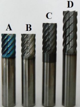
Fig. 1. Milling tools
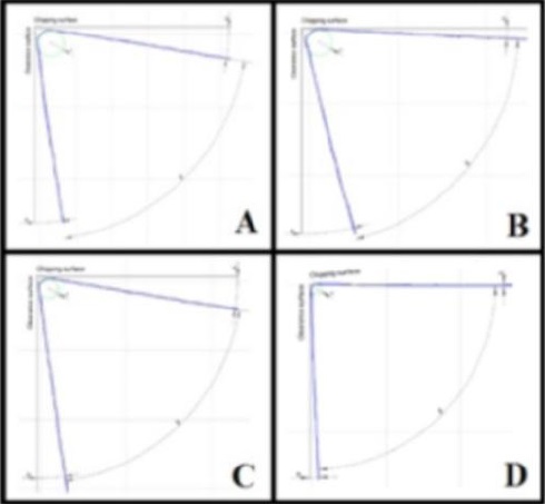
Fig. 2. Sections of cutting edges
Table 1. The basic parameters of cutting tools
Hardened steel DIN X210Cr12 was used in the experiment. A workpiece with dimensions 150x150x17 mm is shown in Fig. 4. Hardness of each plate was 62±2 HRC. The workpiece was clamped by clamps to the KISTLER 9225 A dynamometer (Fig. 4), because cutting forces and their progress were also measured during the experiment. Strategy of side milling is shown in Fig. 5. Material was machined through the entire thickness of the workpiece. All material was removed by the side of the cutting tool. The figure also shows the directions of the components of forces acting on the cutting tool.
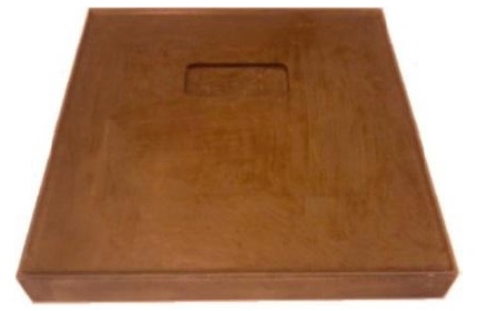
Fig. 3. Workpiece
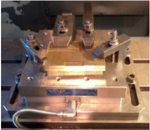
Fig. 4. Clamped workpiece on dynamometer

Fig. 5. Strategy of machining
Material was removed on one side of the workpiece during each pass of the tool. “Observed from the viewpoint of removed material together with flank wear, down milling is more favorable compared to the up milling”, therefore the strategy of climb (down) milling was used. Slice thickness ae was constant for each tool as well as feed per tooth. Depth of cut ap is equal to the thickness of the workpiece. Cutting tools were clamped in a hydraulic tool holder and no cutting fluid was used during machining to avoid thermal shocks. All experimental machining was carried out on MCV 750A vertical CNC center.
In the first part of the experiment, a short-term test according A. S. Kondratov was used to determine optimal cutting speed v15 for durability of 15 min. Each tool was tested and the resulting values of cutting speeds are shown in Table 2. Cutting speed for tool B could not be determined because of destruction of cutting edges during machining.
Table 2. Cutting speeds for durability of 15 min

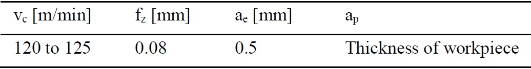
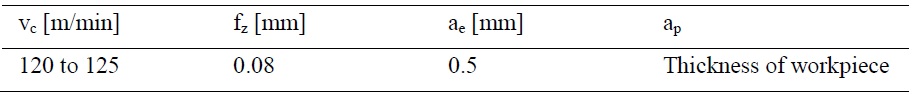
The long-term test was used in the second part of the experiment. All cutting tools A, B, C, D were tested with constant cutting conditions. Cutting speeds were determined from the results obtained in the first part of the experiment. All cutting parameters are shown in Table 3. The machining strategy was the same as in the short-term test.
The testing material was machined with each tool with constant cutting speed. During machining, the flank wears VBB were measured at intervals. Machining continued until the wear reached the critical value VBkrit. Durability for critical value VBkrit = 0.1 mm was obtained for each cutting tool. Total machining time and the amount of material removed during the long-term test ware also obtained. The flank wear was measured on three cutting edges at a constant distance from the face of cutting tools (Fig. 6).
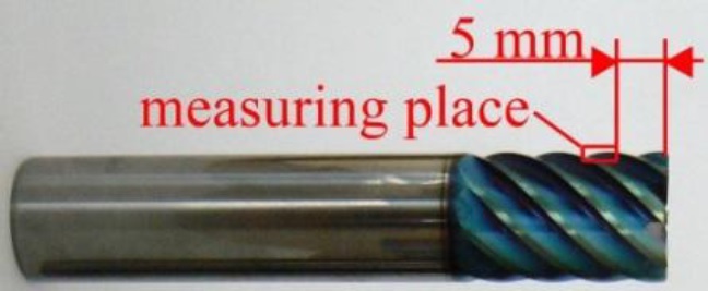
Fig. 6. Measuring place, end mill A
Table 3. Cutting conditions
End mill A is shown in Fig. 6. The flank wear was measured approximately every 2 minutes during machining. For measuring, a Multicheck PC500 optical microscope was used. Flank wear values of end mill A are shown in Table 4. During machining, end mill wear increased evenly (Fig. 7), but parts of the removed material started to stick on the cutting edges of the end mill. At final time TK, flutes of the end mill were clogged by chips due to sticking. It caused cracking of cutting edges and destruction of the end mill. The final state of the end mill is shown in Fig. 9. The influence of clogged flutes is seen on the workpiece surface (Fig. 10). During the last pass of the end mill, high heat was generated due to high friction. The critical value of flank wear was not reached.
The progress of cutting forces was measured and during the last pass, y component of the cutting force Fy increased above 5000 N.
Table 4. Flank wear values, end mill A

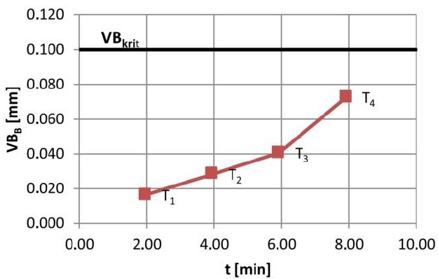
Fig. 7. Progress of flank wear, end mill A
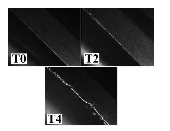
Fig. 8. Flank wear on cutting edge
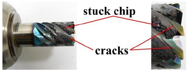
Fig. 9. Final state of end mill A
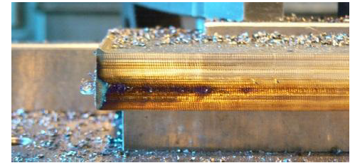
Fig. 10. Workpiece surface after last pass
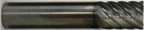
Fig. 11. End mill B
End mill B is shown in Fig. 11. The measuring interval was set approximately at 1 minute to better show the progress of flank wear. Flank wear values of end mill B are shown in Table 5. The critical value of flank wear was reached after the third minute of cutting. Fig. 12 shows the progress of end mill wear over time. Approximately in the fifth minute of milling, flank wear reached a value of VBB = 0.15 mm. During machining, material stuck on the cutting edges and it caused clogging of end mill flutes. This led to damage of cutting edges (Fig. 14). Fig. 13 shows the flank wear on the cutting edge at measuring intervals.
Table 5. Flank wear values, end mill B
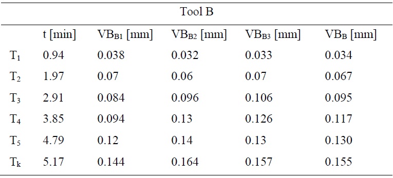
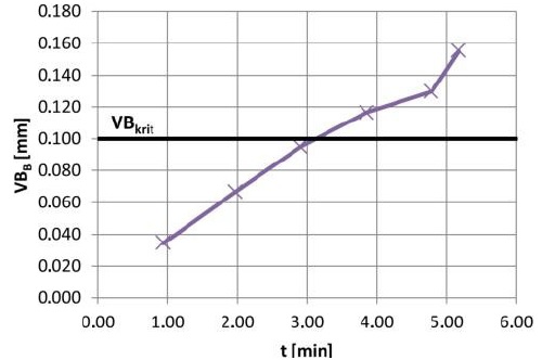
Fig. 12. Progress of flank wear, end mill B
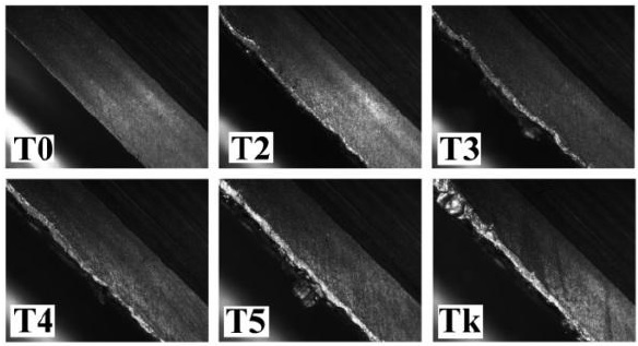
Fig. 13. Flank wear on cutting edge
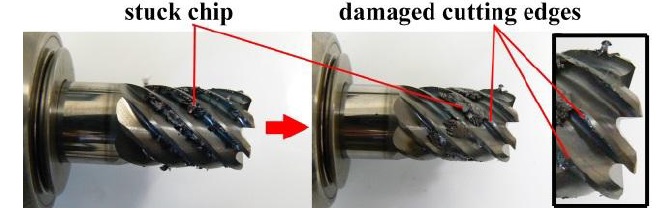
Fig. 14. Final state of end mill B
End mill C is shown in Fig. 15. The flank wear was measured approximately every 2 minutes during cutting as for end mill A. Fig. 16 shows the progress of flank wear over time and all results obtained from measuring are in Table 6. Critical value of flank wear was reached at time t = 27.6 min. Between the fourth and the twenty-fifth minute of machining, the progress of the flank wear was almost linear. After that, the flank wear sharply increased and cutting edges were destroyed. Flank wear at selected times are shown in Fig 17. Before the destruction of the end mill, some built-up edges were created and the same effect of sticking chips occurred as in previous cutting tools (Fig. 18). Before the damage of cutting edges, the y component of the cutting force increased rapidly up to 4000 N.
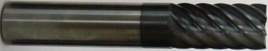
Fig. 15. End mill C
Table 6. Flank wear values, end mill C
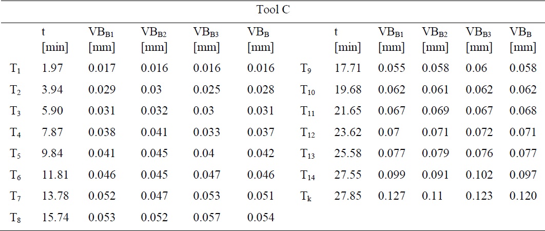
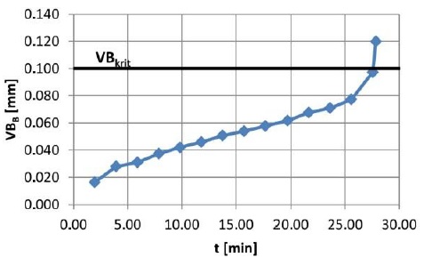
Fig. 16. Progress of flank wear, end mill C
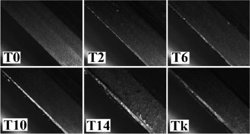
Fig. 17. Flank wear on cutting edge
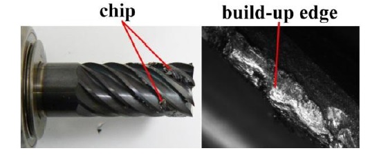
Fig. 18. Final state of end mill C
Critical value of wear flank was reached in time t = 43.47 min. The wear increased equally on all cutting edges (Fig. 20). During machining, the notch wear was created on all flanks of cutting edges of the end mill at the bottom of the workpiece (Fig. 22). The notch wear started at approximately T20 = 37.8 min. At the end of the machining, the size of the notches reached up to 1.2 mm. Because of the large value of the notch on the flanks, experimental machining was ended.
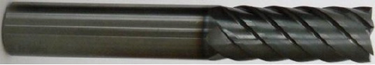
Fig. 19. End mill D
Table 7. Flank wear values, end mill D
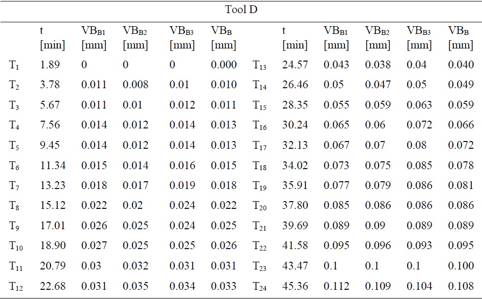
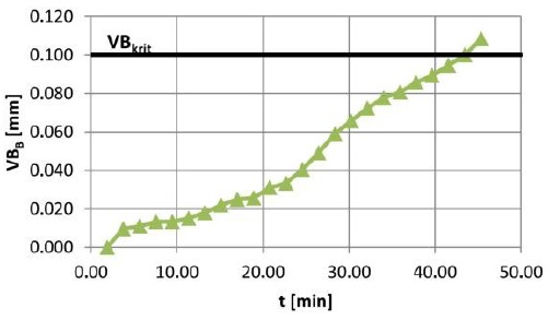
Fig. 20. Progress of flank wear, end mill D
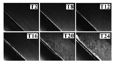
Fig. 21. Flank wear on cutting edge
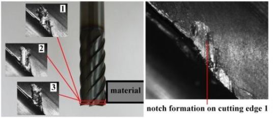
Fig. 22. Notch formation on end mill D
3. Summary of the results
In the first part of the experiment, the short-term test according to A. S. Kondratov was used. The aim of this test was to determine optimal cutting speed for durability of 15 minutes (v15) for each testing tool (A, B, C, D). The results are shown in Table 8. VBBmax is the value of maximum flank wear reached on the tool during the short-time test. For tool B, the cutting speed v15 was not determined because of the cracking of cutting edges during machining. The resulting cutting conditions, used in the second part of the experiment, are shown in the table.
Table 8. Results of short-term test
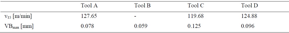
Table 9. Cutting conditions
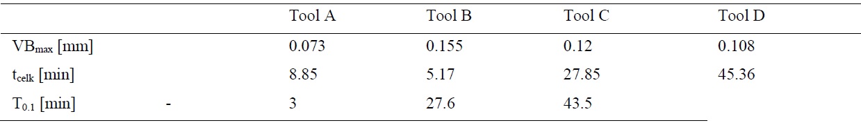
The long-term test was in the second part of the experiment. Hardened steel DIN X210Cr12 was machined with the side milling strategy with each tool. During machining, flank wear was measured on the microscope until it reached the critical value. For this value, durability T0.1 of each tool was determined. The results are in Table 10. The table also shows maximum flank wear VBBmax reached during machining and the total time of machining tfin for each tool. Tool A was the only tool which did not reach the critical value of flank wear. Fig. 23 shows the progress of tool wear for each tool. It is obvious that tool D (WOTEK tool) reached the highest durability of all tools and the critical value of the flank wear was reached after 43.5 minutes of machining. There was no crack formation on tool D during machining, but there was notch wear at the same places on each cutting edge. The WOTEK also achieved the best quality of machined surface from a subjective point of view. In Fig. 25 are shown cutting edges of tools in their finite machining time. Progress of Fy of each tool is shown in Fig. 24.
Table 10. Results of long-term test
Conclusion
Hard and solid materials are very often used in the mechanical engineering industry, for example in production of cutting tools, forming tools or dies and molds. If we want to productively and competitively machine these materials, we must constantly reduce machining costs and increase the quality of machining. This article compares four different milling tools according to their durability during machining of DIN X210Cr12 hardened steel. The big problem was the sticking of the material onto the cutting edges of the cutting tools during machining. This effect occurred with tools A, B and C. This problem caused the destruction of the cutting edges. For tools A and B, flutes were clogged during milling. Tool B had the lowest durability of all the tools. Although tool B reached a high value of flank wear before destruction, the machining time was very short compared to tools C and D. During testing, cutting forces were measured. The dominant component of the cutting force was the y component Fy, which increased with machining time. Other components of the cutting force remained almost constant during machining and did not exceed 600 N. During machining, a large amount of heat was generated.
End mill D (WOTEK end mill) achieved the highest durability. The coating and related processes had the greatest influence on the good results. The appropriate preparation of cutting edge (micro-geometry) and the appropriate choice of carbide substrate provides a good coherence of thin-film and carbide substrate without any defects. The results of this work will be used for further research and development of cutting tools for hard machining.
Acknowledgements
This paper is based upon work sponsored by project SGS-2013-031.