Understanding Molds Definition, Common Applications, and Manufacturing Process
2021-10-08
Definition
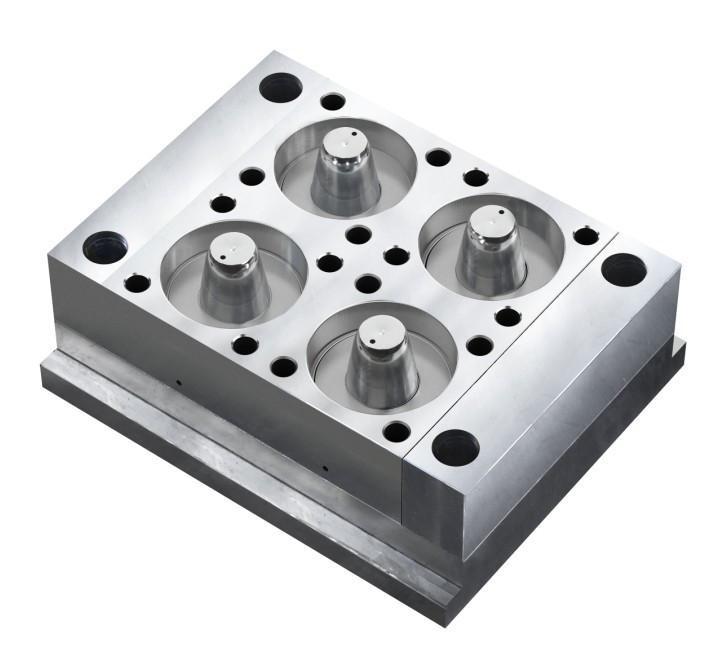
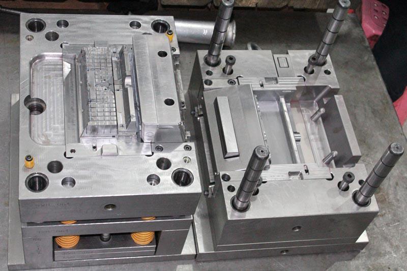
Mold Making refers to the processing of forming and billet making tools, in addition to shear and die cutting dies. Typically, the mold has two parts, an upper mold and a lower mold. By placing the steel plate between the upper and lower dies, the forming of the material is achieved under the action of the press, and when the press is opened, the workpiece determined by the shape of the die is obtained or the corresponding waste material is removed. Workpieces as small as electronic connectors and as large as the dashboard of a car can be molded.
The step advance is a set of molds that can automatically move the workpiece from one station to another and get the formed part at the last station. Die processing processes include: cutting, blanking, compounding, extrusion, four-slide, progressive, stamping, die-cutting, etc.
1. Type of mold
(1) Metal Stamping Die: Continuous Die, Single Stamping Die, Composite Die, Drawing Die.(2) Plastic moulds: injection mould, extrusion mould, blister mould.
(3) Die Casting Die.
(4) Forging dies.
(5) Powder metallurgy moulds.
(6) Rubber mold.
2. Mould price process
Moulding material: front moulding material, back moulding material, inlay material, alignment material, slanted top material.Frame moulding: Front die frame, rear die frame.
Roughing: Front die cavity, rear die cavity, parting line.
Copper core: Front die copper core, rear die copper core, split wire clear angle copper core.
Wire cutting: Inlays, copper core, sloping tops.
Computer gong: Gong die divider cable, gong rear die core.
Spark: Front die coarse, copper male, core wire clearing angle, rear die bone position, occipital position.
Drilling of holes, pin holes, ejectors; machining of line positions, line pressure poles for water line holes in mold ejectors.
Slanted thimble, restoration thimble, matching thimble.
3. Other
(1) Pumping nozzles, dike pits, refuse nails (restriction nails).(2) Flying moulds.
(3) Inlets, supports, springs, water transport.
(4) Die saving, polishing, front die, back die bone position.
(5) Fine water construction, tie rod screw hook, spring.
(6) Heat treatment, quenching and nitriding of critical components.
4. Mould software
UGNX, Pro/NC, CATIA, MasterCAM, SurfCAM, TopSolid CAM, SPACE-E, CAMWORKS, WorkNC, TEBIS, HyperMILL, Powermill, GibbsCAM, FEATURECAM and more.
5. Basic features
(1) Processing accuracy requirements of a pair of molds is generally composed of concave die, convex die and die frame, some may also be multiple pieces of composite modules. Therefore, the combination of upper and lower die, the combination of the block and cavity, and the fit between the modules all require a high degree of machining accuracy. The dimensional accuracy of precision molds often reaches the μm level.(2) The shape of some products such as car coverings, aircraft parts, toys, household appliances, the shape of the surface is composed of a combination of curved surfaces, therefore, the mold cavity surface is very complex. Some surfaces must be treated with mathematical calculations.
(3) Small batch production of molds is not large batch production, and in many cases often only a single batch is produced.
(4) Multi-processes Milling, boring, drilling, reaming and tapping are always used in die and mold processing.
(5) Repeatable cast molds have a life expectancy. When a mold outlasts its life, it has to be replaced with a new one, so there is often duplication in the production of the mold.
(6) imitation processing mold production is sometimes neither drawings, nor data, and to be based on the physical object of imitation processing. This requires high imitation accuracy and no change in shape.
(7) mold material is excellent, high hardness of the main material of the mold is mostly made of high quality alloy steel, especially the high life of the mold, often using Crl2, CrWMn and other lyersonic steel production. This type of steel has stringent requirements from forging and processing of billets to heat treatment. Therefore, the establishment of the processing process should not be overlooked, and heat treatment deformation is also an issue that needs to be taken seriously in processing.
Based on the above-mentioned features, it is important to meet the machining requirements as much as possible on the selected tooling machine. For example, the function of the CNC system should be strong, the accuracy of the tool machine should be high, the rigidity should be good, the thermal stability should be good, the function of imitation, etc.
6. Process flow arrangement
(1) Bottom surface processing, with guaranteed processing capacity.(2) Casting blank standard correction, 2D and 3D surface balance check.
(3) 2D, 3D profile roughing, non-mounting non-working plane machining (including safety platform surfaces, buffer mounting surfaces, platen surfaces, side base surfaces).
(4) The alignment of the side alignment surfaces to ensure accuracy before semi-finishing.
(5) Semi-finishing of 2D and 3D typefaces, finishing of various types of mounting faces (including limiting block mounting faces and contact faces, panel mounting faces and backing faces, punch mounting faces, waste cutter mounting faces and backing faces, spring mounting faces and contact faces, various types of stroke limiting working faces, oblique wedge mounting faces and backing faces), semi-finishing of various types of guiding faces and guiding holes, leaving the balance of finishing process reference holes and height reference faces, and recording data.
(6) Checking double-checking of machining accuracy.
(7) Clampworking process.
(8) Prior to finishing, the base surface of the process reference hole is set and the remaining amount of the block is checked.
(9) Finished faces 2D, 3D, side-punched faces and hole positions, finishing process reference holes and height references, finishing guide faces and guide holes.
(10) Double check machining accuracy.
7. Notes
(1) Concise, detailed and numerical representation of the process content.(2) The key points of processing, the craft should be specially emphasized.
(3) The need for a combined processing office with a clear articulation of the process.
(4) When the block is to be processed separately, pay attention to the processing accuracy of the craft requirements stated.
(5) For block parts that need to be individually machined after combined processing, the process requirements for installing individually machined benchmarks for combined processing.
(6) The springs are the most susceptible to damage during die processing, so choose a die spring with a long fatigue life.
Large die mold processing problems
1. Great size and weight.
When machining large molds, coping with their own enormous size and weight is a major challenge for processing companies. The processing of large molds often requires a lot of labor, special equipment and multiple debugging clamps, and the machining accuracy is not easy to guarantee due to the influence of many potential factors.
2. Acquisition cost issues
The largest cost directly related to the processing of various large moulds is the acquisition cost of the tooling machine. Tooling machines capable of producing large molds are expensive, especially in complex process arrangements where multiple tooling machines are required to complete the entire process from roughing to finishing of the mold. Such high upfront investment costs are also the biggest barrier for many companies to enter this market. From this, we can see that if the roughing and finishing of large moulds can be achieved on a suitable tooling machine, even with a single adjustment of the clamps, many problems will be solved and machining accuracy can be guaranteed.
CNC milling machine
1. Cast iron bed structure, tool machine spindle has heat dissipation function.
Cast iron has high rigidity and heat dissipation properties, making it the most stable material for the manufacture of tool components. For any tooling machine used for milling large parts, it is first necessary to have a very strong cast iron construction and to have a spindle with a heat dissipation function.In the case of the spindle of a tooling machine, it must be cooled from the outside of the bearing by means of an internal cooling technique, which guarantees that the spindle itself will not be burned out or lose accuracy due to thermal expansion during the long machining process. These factors are very important because the machining of large dies takes a long time to consume, and under heavy cutting conditions, this increases the heat and stress on the die. Therefore, the structural components of the tooling machine must have good rigidity and heat dissipation properties, which are the prerequisites for processing large, high-quality molds. Therefore, the vibration of the tooling machine during the process must be limited to the maximum extent possible and the heat generated during the process must be rapidly diffused. Choosing the right machine and tool for machining can be a win-win for both cost and cycle time.
2. Thermal Stability Technology
Due to the long cutting time, the effect of the ambient temperature must also be considered. For example, when processing a large mold on an ordinary tooling machine, when the ambient temperature changes by 10°C, it will cause a 6°C temperature change in the tooling machine column, which will cause a 0.07mm change in the parallelism of the spindle angle plate. Therefore, the design of the tooling machine must take into account the effect of ambient temperature to avoid the ambient temperature affecting the accuracy of the machined parts.
3. Speed
For a large mold machining center that can move quickly, the spindle speed of the large mold machining tool machine should reach at least 20,000r/min, and the metal cutting speed should meet 762~20,000mm/min.
4.Accuracy
If roughing and finishing of large moulds is to be achieved on a machining center, the positioning accuracy and repeatability of the tooling machine must be strictly controlled. The machining center for large mold, the general positioning accuracy can reach ± 1.5μm, the repeat positioning accuracy should reach ± 1μm, at the same time, the pitch accuracy should be kept within 5μm.
5. Feedback Resolution
For high-precision surface machining, the machine's own feedback resolution is very important to check the accuracy of the machined parts. Using a standard 1μm feedback resolution, the results are usually not very good. If the resolution can reach 0.05μm, then the finishing results are almost flawless. Moreover, the quality of the surface of the part can be further improved by the control of machine resolution, scale feedback and small pitch ball screws.
6. Spindle
Spindles used on large mold machining centers must meet the requirements for roughing, semi-finishing and high quality finishing, and as a reference standard, the surface finish quality that can be achieved should be controlled to a level of 2μm. Usually, finishing is important for the closing surface and parting line parts of the mold, but under traditional processes, many mold makers have to resort to hand polishing to compensate for the lack of precision in tooling. The reason is that large machining tools are expensive and it is obviously impractical to purchase multifunctional tools for this process.In addition, a reasonable spindle design must be able to maximize the life of the tool so that it can operate continuously with low vibration and low temperature rise during the machining cycle. For example, in the large mold machining center on the processing of automotive dashboard mold, such as the use of 16mm CBN insert finishing tool, the processing speed can reach 8m/min, the service life of more than 30h, the processing surface quality control in 0.336 ~ 3.2μm. From this, considering the processing of large mold tool cost increases, the use of specially designed large mold machining tool machine, not only can extend the life of the tool, but also can save a lot of processing tool cost per pay mold.
7. Movable multi-axis machining head
Due to mold size and weight limitations, it generally takes a long time to load the workpiece. As a result, the use of 3-axis machining centers not only reduces the number of workpieces to be debugged, but also does not affect the machining accuracy of the tooling machine, thus greatly increasing the production capacity of the workshop for machining large molds.The movable multi-axis head can be used to machine large molds with particularly complex structures, and the variable geometry design of the head allows for 3-axis machining, milling deep cavities and cooling holes, as well as cutting many other geometrically complex parts in a single clamping operation. For example, when the spindle is tilted at an optimal angle, the proximity of the head to the milling work point can be increased, which makes it possible to complete the machining of beveled holes using multi-axis heads.
In addition, the surface roughness can be improved by using the radius cutting edge of a tungsten carbide end mill instead of the tip of a tungsten carbide end mill when machining the workpiece surface with a multi-axis head.
8. Chip management
The metal cutting process generates a large amount of chips which, if not eliminated in time, will inevitably lead to secondary cutting and a temperature rise on the structural parts of the machine or the workpiece surface. Large mold machining centers typically have 18 chip removal holes underneath the table to reliably remove chips no matter where the table is moved. There are 4 internal hinged chip conveyor belts on the tool machine that discharge chips to the front of the tool machine at a very high speed.
9. High Pressure Coolant
High-pressure coolant plays a very important role in the processing of large moulds. For example, when drilling beveled holes using the 2+3 axis method, a coolant with a pressure of 1000 psi (1 psi = 6890 Pa) is required to effectively remove chips and achieve a more accurate cut. Without this high-pressure coolant, additional tooling machines would need to be added when machining beveled holes, requiring secondary card loading, reducing machining accuracy and increasing cycle costs. According to the above analysis, it can be seen that the realization of simple processing of large molds requires more and better functions of the tool machine.The new MCC2516VG3 horizontal machining center developed by Makino has a spindle speed of up to 15000r/min and adopts the "core cooling" method and "internal pressure lubrication of bearings" function to ensure timely and effective cooling of the spindle and its auxiliary bearings.
In addition, the spindle can be rotated not only along the horizontal X-axis, vertical Y-axis and front and rear Z-axis, but also with A-axis and C-axis. Thanks to the 2 indexing functions, not only is it possible to reduce the amount of adjustment, but it is also possible to cut complex structures such as bumpers, dashboards and headlight lenses.