The Influence of Different Types of Copy Milling on the Surface Roughness and Tool Life of End Mills
2020-06-04
Abstract
The article deals with the tool life of ball nose end mill depending on up-copying and down-copying. The aim was to determine and compare the wear of ball nose end mill for different types of copy milling operations for various tool materials. Moreover, surface roughness in up-copying and down-copying was also measured and compared. In addition, we examined and observed cutter contact areas of ball nose end mills with machined material. For wear test, DMG DMU 85 monoBLOCK 5-axis CNC milling machine was used. In the experiment, the cutting tool material was changed and on the other hand cutting speed, feed rate, axial depth of cut and radial depth of cut were not changed. The cemented carbide and high speed steel were tested as tool materials. The cutting tool wear was measured on Zoller Genius 3s universal measuring machine. Surtronic 3+ (Taylor Hobson) was used for surface roughness measurement. The results show different surface roughness and tool life of ball nose end mills depending on the copy milling strategy for various tool materials.
1. Introduction
A copy milling tool path is often a combination of up- and downmilling, and requires a lot of unfavourable engagements and disengagements in the cut. During the free form surface milling, dies and moulds can be machined either upwards or downwards. The position of the tool in relation to the machined surface (inclination angle) has a strong impact on the cutting forces. The angle between the tool and work surface has a direct impact on the length and position of an active cutting edge of an arch-shaped mill, which in turn significantly affects the cutting process. An incorrect tool position may cause a sudden increase in cutting force and/or tool tip temperature above their respective critical values. Schulz and Hock used ball end mills with different tilt angles to study tool life and workpiece quality, and they concluded that the down-milling/reverse cut with a tool inclination in the range of 10°~20° represents the optimum machining strategy for high-speed milling in the mould and die making industry.
Chen optimized the tool path of the ball-end milling cutter based on surface error, which is defined by the deviation of the real motion of the tool. The tool path is essential in order to machine an accurate 3D surface. Toh collected the effects of the tool path and orientation to the cutting force, the tool life and surface quality. The path orientation defines the size of the chip contact area and the inclination angle has optimum value from the viewpoint of the tool life. The inclination angle in case of free-form surface 3D milling is changed point-by-point but in case of 5D milling it can be constant. The tool position can easily be corrected on a 5-axis CNC machine, which is more expensive to purchase and maintain, and thus has the higher amortization costs. The two critical issues encountered during machining are: short tool life, and difficulty to deliver the required surface finish. Zetek et al. observed flank wear and measured cutting forces during the face milling of Inconel 718. They optimized size of edge radius and increased tool life about 20%. Kasim et al. found that notch wear was the predominant failure mode during end milling of Inconel 718. Begic-Hajdarevic et al. investigated the effect of cutting parameters on surface roughness in up- and downmilling. In recent study, the wear measurement process of carbide ball nose end mill was examined. In this experiment, the influence of up-copying and down-copying on the surface roughness and tool life of ball nose end mills was determined and compared for various tool materials.
2. Materials and experimental methods
2.1. Workpiece material
The selected workpiece material was medium-carbon steel of ISO C45 (AISI 1045) grade. Chemical composition and mechanical properties are shown in Tables 2 and 3. Block material had dimensions of 100×100×60 mm. Model of workpiece was carried out in CAD system.
Table 1. Chemical composition of machined material C45.

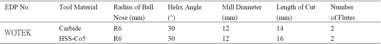
2.2. Tested cutting tools
Application of ball nose end mill (specimen) is typical for mould milling. It is related to the kinematics representation of ball nose end mill in copy milling. The tested cutting tool materials were uncoated cemented carbide (MicroGrain) and high speed steel (HSS-Co5).
We studied four specimens:
•S1 - carbide ball nose end mill for up-copying
•S2 - carbide ball nose end mill for down-copying
•S3 - HSS-Co5 ball nose end mill for up-copying
•S4 - HSS-Co5 ball nose end mill for down-copying
Parameters of WOTEK ball nose end mills are shown in Table 2. Every of them were used for copy milling operations, since we investigated influence of cutter contact areas on the cutter plane on wear of ball nose end mill, which is due to the change of cutter contact area of cutting tool in copy milling operations according to up-copying and down-copying.
Table 2. Parameters of WOTEK ball nose end mills
2.3. Tool life test and surface roughness measurement
For copy milling, DMG DMU 85 monoBLOCK 5-axis CNC milling machine was used (Fig. 1a). First, the program for CNC machine tool was generated in a CAM system. Coolant was not used in the machining process. For cutting tests, we set the same cutting conditions (cutting speed, feed rate, axial and radial depth of cut). Hence, we intended to investigate just the influence of cutter contact areas on the cutter plane on wear of ball nose end mill for the same cutting parameters. The inclination angle of the workpiece was 15°. Tonshoff et al. found that the optimum inclined angle is 15° for ball end-milling of block materials.
Since the flank wear of ball nose end mill was dominant, it was measured on Zoller Genius 3s universal measuring machine (Fig. 1b). The flank wear was measured every 10.75 min equivalent to 2 m length of cut. The machining tests for carbide mills were stopped when the flank wear reached over 0.3 mm and 0.2 mm for HSS-Co5 mills. Since the edge chipping was observed over these values. Moreover, surface roughness of workpiece material was measured after 10.75 min of cutting and subsequently when ball nose end mills reach flank wear criterion (0.3 mm for carbide mills and 0.2 mm for HSS-Co5 mills). Surtronic 3+ was used for surface roughness measurement.
%20workplace%20of%20DMG%20DMU%2085%20MonoBLOCK%3B%20(b)%20measuring%20of%20flank%20wear%20on%20Zoller%20Genius%203s.jpg)
Since the flank wear of ball nose end mill was dominant, it was measured on Zoller Genius 3s universal measuring machine (Fig. 1b). The flank wear was measured every 10.75 min equivalent to 2 m length of cut. The machining tests for carbide mills were stopped when the flank wear reached over 0.3 mm and 0.2 mm for HSS-Co5 mills. Since the edge chipping was observed over these values. Moreover, surface roughness of workpiece material was measured after 10.75 min of cutting and subsequently when ball nose end mills reach flank wear criterion (0.3 mm for carbide mills and 0.2 mm for HSS-Co5 mills). Surtronic 3+ was used for surface roughness measurement.
Fig. 1. (a) workplace of DMG DMU 85 MonoBLOCK; (b) measuring of flank wear on Zoller Genius 3s.
2.4. Cutting conditions All tool life tests were carried out with the following parameters:
cutting speed vc = 70 m/min, spindle speed n = 1856.8 1/min, feed rate vf = 186 mm/min, axial depth of cut ap = 0.5 mm, radial depth of cut ae = 0.5 mm, feed per tooth fz = 0.05 mm.
2.5. Effective cutting radius and effective cutting speed in copy milling
In up-copying, tangential curve is placed on the one side from the axis of rotation of ball nose end mill. In downcopying, tangential curve is placed around the axis of rotation of ball nose end mill on the both sides, and crosses the center of rotation of ball nose end mill. The scheme with symbols for copy milling is shown in Fig. 2.
%20Scheme%20of%20up-copying%3B%20(b)%20scheme%20of%20down-copying.jpg)
Fig. 2. (a) Scheme of up-copying; (b) scheme of down-copying
The symbols in Fig. 2:
R - radius of the cutter (mm)
ap - depth of cut (mm)
vf - feed rate (mm/min)
ap,max - maximum depth of cut (mm)
α - slope angle of milling surface (°)
ap,iden - identical depth of cut (mm)
n - spindle speed (1/min)
ap,crit - critical depth of cut (mm)
Ref1 - effective radius of the cutter
Ref2 - effective radius of the cutter on machined surface (mm) on work surface (mm)
Determination of effective radius is very important for obtaining the effective cutting speed. Equations for effective radius and effective cutting speed have the following forms.
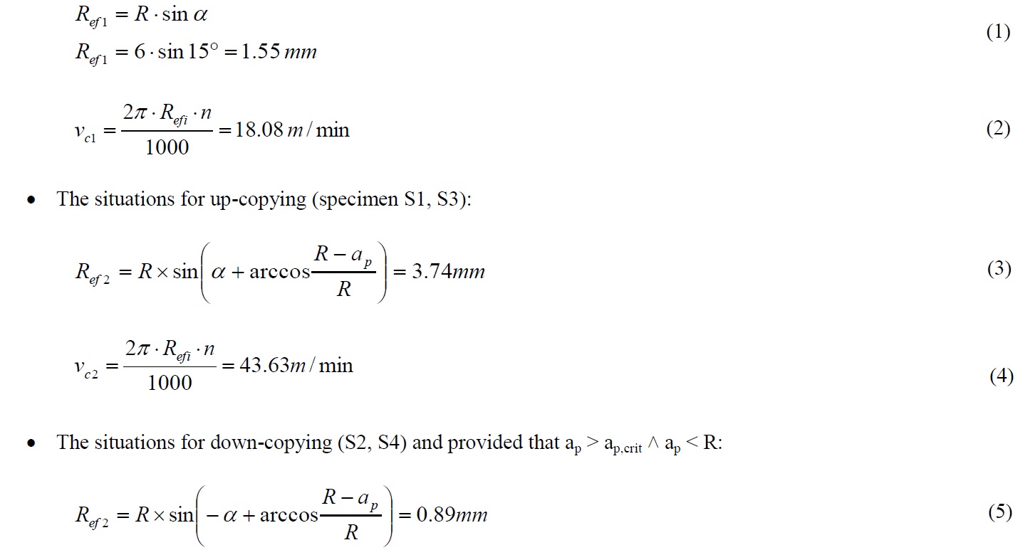
From the equation for effective cutting speed results that the highest cutting speed is calculated for the larger of the effective radius Ref1 and Ref2. Therefore, in up-copying (equation 3), Ref2 > Ref1, the effective cutting speed was calculated for Ref2 (equation 4). Since in down-copying (equation 5), Ref2 < Ref1, the effective cutting speed was calculated for Ref1 (equation 2).
ap - depth of cut (mm)
vf - feed rate (mm/min)
ap,max - maximum depth of cut (mm)
α - slope angle of milling surface (°)
ap,iden - identical depth of cut (mm)
n - spindle speed (1/min)
ap,crit - critical depth of cut (mm)
Ref1 - effective radius of the cutter
Ref2 - effective radius of the cutter on machined surface (mm) on work surface (mm)
Determination of effective radius is very important for obtaining the effective cutting speed. Equations for effective radius and effective cutting speed have the following forms.
From the equation for effective cutting speed results that the highest cutting speed is calculated for the larger of the effective radius Ref1 and Ref2. Therefore, in up-copying (equation 3), Ref2 > Ref1, the effective cutting speed was calculated for Ref2 (equation 4). Since in down-copying (equation 5), Ref2 < Ref1, the effective cutting speed was calculated for Ref1 (equation 2).
3. Results
3.1. Measured flank wear in micrographs
The measured flank wear is shown in Fig. 3 and Fig. 4. Micrographs of flank of carbide ball nose end mills are shown in Fig.3 and micrographs of flank of HSS-Co5 ball nose and mills are shown in Fig. 4. The first two columns are micrographs of flank wear for up-copying. The other two columns are micrographs of flank wear for down-copying. Fig. 3a and Fig. 4a record ball nose end mills before cutting in time of 0 min. Furthermore, Fig. 3b and Fig. 4b show measured flank wear after attaining the value over 0.3 mm for carbide mills and 0.2 mm for HSS-Co5 mills. The edge chipping was observed just over these values (Fig. 5).
%20carbide%20ball%20nose%20end%20mill%20before%20cutting%2C%20(b)%20flank%20wear%20after%20attaining%20the%20value%20of%200_3%20mm.png)
Fig. 3. (a) carbide ball nose end mill before cutting, (b) flank wear after attaining the value of 0.3 mm
%20HSS-Co5%20ball%20nose%20end%20mill%20before%20cutting%2C%20(b)%20flank%20wear%20after%20attaining%20the%20value%20of%200_2%20mm.jpg)
Fig. 4. (a) HSS-Co5 ball nose end mill before cutting, (b) flank wear after attaining the value of 0.2 mm
%20edge%20chipping%20of%20carbide%20mill%20for%20up-copying%2C%20(b)%20edge%20chipping%20of%20HSS-Co5%20mill%20for%20down-copying.jpg)
Fig. 5. (a) edge chipping of carbide mill for up-copying, (b) edge chipping of HSS-Co5 mill for down-copying
3.2 The evaluation of tool life test
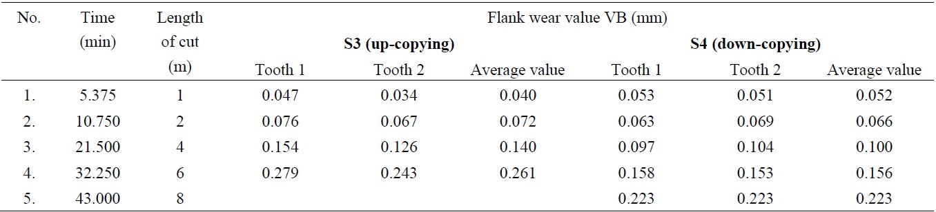
The next step of the wear measurement process was evaluation of the tool life test. First of all, the calibration process of measurement system of Zoller Genius 3S was initiated before the milling. The particular wear measurements were implemented for the first and then the second cutting edge. The average value was determined and inserted to Tables 3.
Flank wear values for specimens S1, S2, S3 and S4 are also described in Table 3 and 4. For S1, the flank wear value reached over 0.3 mm after 64.5 min of cutting. As can be seen in measurement No. 7, the flank wear value on the second tooth is same as the flank wear value in measurement No. 6. It is caused by edge chipping. The flank wear increased, but chipping of cutting edge caused that the measured value of flank wear decreased due to the chipping. For S2, the flank wear value reached over 0.3 mm after 86 min of cutting. For S3, the flank wear value reached over 0.2 mm after 32.25 min and for S4 after 43 min.
Flank wear values for specimens S1, S2, S3 and S4 are also described in Table 3 and 4. For S1, the flank wear value reached over 0.3 mm after 64.5 min of cutting. As can be seen in measurement No. 7, the flank wear value on the second tooth is same as the flank wear value in measurement No. 6. It is caused by edge chipping. The flank wear increased, but chipping of cutting edge caused that the measured value of flank wear decreased due to the chipping. For S2, the flank wear value reached over 0.3 mm after 86 min of cutting. For S3, the flank wear value reached over 0.2 mm after 32.25 min and for S4 after 43 min.
Table 3. Flank wear values of carbide ball nose end mills for different types of copy milling
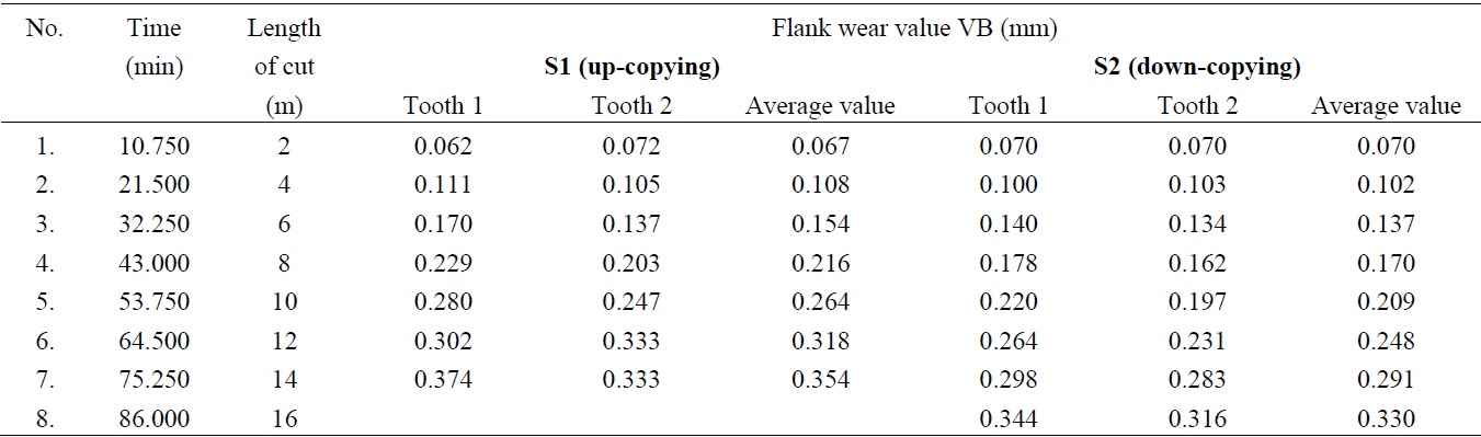
Table 4. Flank wear values of HSS-Co5 ball nose end mills for different types of copy milling
The graph in Fig. 6 plotted based on flank wear value of particular measurement expresses the time dependence of flank wear. The time dependence of flank wear for specimens S1, S2, S3 and S4 was then compared.
As can be seen from the graph, the tool life of samples for down-copying is longer than for up-copying. In case of carbide mills, the tool life of S2 is 40% longer than S1. For HSS-Co5 mills, the tool life of S4 is 50% longer than S3. We suppose that it is due to various effective radiuses which are mentioned in chapter 2.5. Thus, the effective cutting speed is changed by different effective radius. The effective cutting speed in up-copying is 2.41 times greater than in down-copying. The importance of cutting speed can be seen from the Taylor’s equation, as the formula relies only on the cutting speed to estimate tool life. Equation 6 is also called Taylor tool-life equation. From this equation, it results that the increase of cutting speed leads to decreasing the tool life. From this reason, the tool life of mills in down-copying is longer than mills in up-copying due to lower effective cutting speed.

where:
vc – cutting speed (m/min)
Tc1/ k - Taylor’s exponent
C - constant.
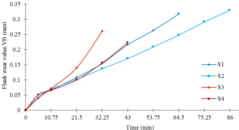
Fig. 6. The time dependence of flank wear
3.3. The evaluation of surface roughness measurement
The comparison of measured surface roughness of workpiece material for ball nose end mills (S1, S2, S3 and S4) is shown in Fig. 7. Every measurement was performed five times. The results of roughness measurement show Ra in up-copying is better than in down-copying.
After 10.75 min of cutting, measured arithmetic average roughness (Ra) was:
•in up-copying: for carbide mill (S1) Ra = 1.16 μm and for HSS-Co5 mill (S3) Ra =1.54 μm
•in down-copying: for carbide mill (S2) Ra = 1.58 μm and for HSS-Co5 mill (S4) Ra =2.41 μm
•in down-copying: for carbide mill (S2) Ra = 1.58 μm and for HSS-Co5 mill (S4) Ra =2.41 μm
After reaching of flank wear criterion, arithmetic average roughness (Ra) was:
•in up-copying: for carbide mill (S1) Ra = 1.69 μm and for HSS-Co5 mill (S3) Ra =2.07 μm
•in down-copying: for carbide mill (S2) Ra = 2.02 μm and for HSS-Co5 mill (S4) Ra =3.42 μm
•in down-copying: for carbide mill (S2) Ra = 2.02 μm and for HSS-Co5 mill (S4) Ra =3.42 μm
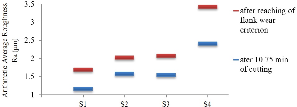
Fig. 7. Surface roughness in up-copying and down-copying
Conclusion
The aim was to determine influence of different types of copy milling on the surface roughness and tool life of end mills. The tool wear criterion was the flank wear, because it was dominant. We investigated two tool materials (cemented carbide and HSS-Co5), four cutting tools (specimens S1, S2, S3 and S4) and there were set the same cutting conditions. The worn cutter contact areas of ball nose end mill was first calculated and then observed on Zoller Genius 3s universal measuring machine. For tool life test, DMG DMU 85 monoBLOCK 5-axis CNC milling machine was used.
The results showed different tool life of samples according to type of copy milling. The tool life of samples for down-copying is longer than for up-copying. For carbide mills, the tool life of S2 is 40% longer than S1 and in case of HSS-Co5 mills, the tool life of S4 is 50% longer than S3. We suppose that the tool life of mills in down-copying is longer than mills in up-copying due to lower effective cutting speed during the copy-milling.
Hence, selection of down-copying operation is preferable for copy milling for the case finishing mould, when the tool life is the main criterion. On the other hand, the cutting tools in up-copying show lower values of Ra. The future study will be complemented by regrinded and honed mills. It will be oriented to influence of edge
preparation on the tool life of ball nose end mills in die and mould milling.
Acknowledgements
This contribution is a part of the GA VEGA project of Ministry of Education, Science, Research and Sport of the Slovak Republic, No. 1/0615/12 “Influence of 5-axis grinding parameters for geometric precision of cutting shank tool”. This contribution is also supported by the Operational Project Research and Development of Centre of Excellence of five axis machining, ITMS 26220120013, co-financed by European Funds for Regional Development.