A Performance Comparison Study of Uncoated and TiAlN Coated Carbide End Mill on Machining of the Al-35Zn Alloy
2020-06-23
Abstract
In this study, Al-35Zn alloy was produced by permanent mold casting. To investigate the cutting performance of uncoated and TiAlN coated carbide end mills on this alloy, a series of tests were carried out in the CNC vertical machining center at a constant cutting speed, feed rate and depth of cut. The results obtained from the tests showed that uncoated carbide end mill have lower cutting force and surface roughness than TiAlN coated carbide end mill. These observations are discussed in terms of the alloys properties, cutting tool surfaces, and friction and wear behavior between the cutting tool and the material.
1. Introduction
Due to some advantages over traditional industrial alloys such as cast iron, bronze and brass, aluminum-based alloys are heavily preferred, especially in the automotive, aerospace and aerospace industries. The most important advantages of these alloys are easy and economical production, high specific strength, superior wear and corrosion resistance, and ideal tribological behavior even under overload and inadequate lubrication conditions. Aluminum based alloys are used in the above mentioned industries especially for the manufacturing of spare parts such as sliding bearing, carburetor, cylinder lid, gearbox cover, engine feet, connecting rod and rim. The surface finishing, service life and friction behavior of these parts depend on their surface roughness that reaches its final value after machining. The surface finishing of these parts also significantly affects their fatigue strength, corrosion resistance, and tribological properties. Therefore, the measurement and characterization of surface roughness in the aluminum based alloys is important for the optimization of machining operations. Many factors such as cutting speed, feed rate and cutting tool geometry effect the machining of these alloys. These factors also have a great effect on the formation of cutting forces, surface roughness and build up edge (BUE) formation during the machining. Formation of BUE and build up layer (BUL) are important determinants on the average surface roughness (Ra) values of the work pieces. As the hardness of the aluminum alloys increases, the surface roughness and the formation of BUE decrease. Formation of BUE is accelerated by deactivating the coating, which causes the cutting tool geometry to change. On the other hand, the surface roughness decreased with the increasing of the BUE in short-time cutting operations. In the study of turning the AA7075 alloy, it was observed that as the cutting speed increased, the formation of stacked chips on the cutting tool decreased, which led to a decrease in surface roughness. It is known that in the milling of Al-7075 alloy, it is necessary to use low feed, high cutting speeds for optimum surface quality, and surfaces treated with carbide cutters are better than HSS and TiN coated cutters. It has been suggested that Al-5083 alloy is milled with twoflutes carbide end mill with high cutting speed and low feed rate in terms of good surface quality. In the case of Al-5083 alloy milling with uncoated end mills, it was found that cutting force and surface roughness decreased with increasing cutting speed, but burr height increased. In this study, to determine of the machinability of the Al-35Zn alloy, it was tested with uncoated and TiAlN coated carbide end mills under constant cutting speed, feed rate and depth of cut conditions.
2. Material and method
The Al-35Zn alloy was prepared using commercially pure aluminium (99.8 wt.%) and high purity zinc (99.9 wt.%). These alloying elements were melted in an induction-melting furnace and poured at a temperature of approximately 680 °C into a steel mold having a conical shape. Samples taken for the structural analysis were prepared by standard metallographic methods and etched dispersed in a 2% NaOH solution and examined in light and scanning electron microscope (SEM). The cutting tests were performed with alloy samples having the dimensions of 80x50x10 mm and repeated at least three times. A technical drawing of cutting test sample is given in Fig. 1. The cutting parameters used in the tests are given in Table 1. The cutting tool performance in the milling of test samples with both uncoated and TiAlN coated carbide end mills coated with PVD method at 900 °C was investigated experimentally in terms of cutting force and surface roughness. The coated end mills have a hardness of 3300 HV, a coating thickness of 3 μm and a friction coefficient of 0.3-0.35.
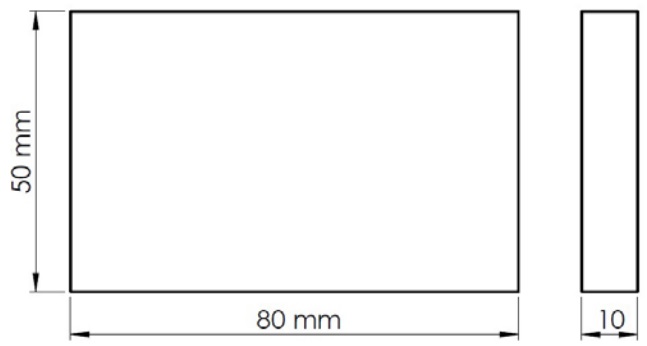
Figure 1. Technical drawing of cutting test sample
Table 1. Cutting parameters

The cutting tests were carried out under dry conditions at a CNC vertical machining center of the Johnford-VMC 850 brand at a power of 7.5 kW. The schematic representation of the testing apparatus is shown in Fig. 2. Cutting tools were end mills with 6 mm diameter, 30° helix angle and h10 quality. The cutting forces generated during the milling of the work piece were measured using a Kistler 9273 model dynamometer and an amplifier. The cutting forces are calculated as the resultant of the forces generated in the X, Y and Z-axes. Mahr Perthometer M1 (MarSurf PS1) tracer surface roughness device (Fig. 3) was used for surface roughness measurements. Sampling length was determined as 0.8 mm and measurement length as 4 mm with the help of standard tables. Average surface roughness (Ra) values, one of the criteria for machinability, are based on the ISO 4287 standard and the surface roughness values are calculated by the arithmetic mean of the deviations in the roughness profile on the machined surfaces. The values of shear force and surface roughness were determined by taking the average of the data obtained from three tests. Machined surfaces and chips examinations were performed with a SEM and optical microscope.
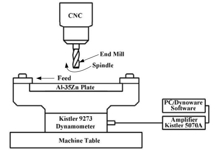
Figure 2. The schematic representation of the testing apparatus
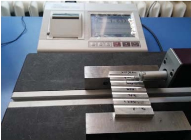
Figure 3. Surface roughness testing apparatus
3. Results and Discussion
SEM micrograph showing the microstructure of the tested alloy is given in Fig. 4. It was observed that microstructure of this alloy consists of aluminum-rich α dendrites and zinc-rich η phase surrounding these dendrites, Fig. 4. Formation of these microstructures of the Al-Zn alloys was related to the phase transformations that take place during solidification of these alloys.
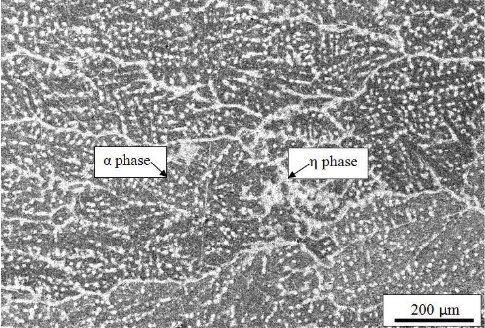
Figure 4. SEM micrograph showing the microstructure of the Al-35Zn alloy
The values of cutting force and surface roughness obtained from the cutting tests are given in Table 2. The cutting force and surface roughness values were found to be higher in the tests used coated cutting tools than in the tests used uncoated end mills, Table 2. Coating can increase cutting performance of end mills by increasing wear resistance of it. However, the coated cutting tools in the machining of aluminum based alloys reduce the contact surface area between the work piece and the cutting tool by reducing the sharpness of the cutting edge. This leads to an increase in cutting forces and surface roughness, as seen in Table 2, in the machining of aluminum-based materials. Cutting forces and surface roughness can be controlled with coated cutting tools with a lower grain size. Thus, the cutting area is reduced by reducing the contact area between the cutting tool cutting edge and the work piece surface.
Table 2. Experimental results

%20uncoated%20end%20mills%20b)%20coated.jpg)
Figure 5. Form of chips obtained from cutting test carried out with a) uncoated end mills b) coated end mills
It was observed that more wear materials are adhered to the cutting edge of coated carbide end mill compare to uncoated tools, Fig. 6. This is because transfer of heat generated in the cutting zone due to pressure and friction during the machining with the coated end mill is more difficult. The difficulty of heat transfer increases the temperature in the cutting zone and leads to increment in ductility of the α and/or η phases, Fig. 4. This increase in ductility causes the chips to adhere to the cutting tools. BUE formation in the cutting tool results in increased cutting force and adversely affects the quality of the surface quality (Fig. 3b and 4). It has been observed in many studies that cutting tools with a low coefficient of friction as well as high cutting speeds and low feed rates are recommended to prevent BUE.
%20Uncoated%20carbide%20end%20mill%2C%20b)%20Coated%20carbide%20end%20mill.jpg)
Figure 6. a) Uncoated carbide end mill, b) Coated carbide end mill
Smearing and scratches were observed to be the main features of the machined surface of the alloy samples, Fig. 7. Smearing takes place by back transferring of the chips, scratches occur due to the removal of chips from the surface of the samples and contact of the abrasive particles adhered to the end mills to the sample surface during machining. Smearing material due to effects of shear stress and frictional heat. More smearing were observed in the tests carried out with coated end mills. This may be due to more heat build-up in the tests carried out with coated end mills than with the tests carried out with uncoated end mills.
.jpg)
Figure 7. SEM micrographs showing the cutted surfaces of the samples of the alloy tested with (a) uncoated end mills b) coated end mills
4. Conclusions
(1) Microstructure of the Al-35Zn alloy consists of aluminum-rich α dendrites and inter dendritic zinc-rich η phase.
(2) Machining of the Al-35Zn alloys with TiAlN coated cutting tools is require more cutting force than machining with uncoated tools.
(3) TiAlN coated cutting tools causes more surface roughness than uncoated tools in machining of the Al-35Zn alloy.
(4) Smearing and scratches are the main features of the machined surface of the Al-35Zn alloy.
(5) Build up edge (BUE) forms on cutting edge of the TiAlN coated cutting tools during the machining of the Al-35Zn alloy.