Two-component end mills with multilayer composite nano-structured coatings as a viable alternative to monolithic carbide end mills
2020-07-02
Abstract
The paper deals with the challenges of the application of two-component end mills, which represent a combination of a carbide cutting part and a shank made of cheaper structural material. The calculations of strains and deformations of composite mills were carried out in comparison with solid carbide mills, with the use of the finite element method. The study also involved the comparative analysis of accuracy parameters of machining with monolithic end mills and two-component end mills with various shank materials. As a result of the conducted cutting tests in milling aluminum alloy with monolithic and two-component end mills with specially developed multilayer composite nano-structured coatings, it has been found that the use of such coatings can reduce strains and, correspondingly, deformations, which can improve the accuracy of machining. Thus, the application of two-component end mills with multilayer composite nano-structured coatings can provide a reduction in the cost of machining while maintaining or even improving the tool life and machining accuracy parameters.
1. Introduction
The cost of operation of modern machining equipment is very high, and that fact results in the need to tighten the operating conditions of cutting tools and in the increase in the proportion of expenses for cutting tools in production costs. Meanwhile, increasing global competition makes it necessary to use all the resources to reduce production costs and increase the efficiency of production. As part of the solution to this challenge, reduction of expenses for cutting tools plays a significant role while maintaining their high-performance cutting properties and reliability. According to S.I. Gonyalin, in 2012, the production volume of cutting tools amounted to 40 billion USD. A significant portion of the above production volume is taken by carbide end mills, which have been widely used in modern mechanical-engineering production. Along with monolithic carbide mills, milling cutters with mechanical fastenings of carbide inserts are also used; however, it is difficult to use mills of such a design with a small cutter diameter (as a rule, it is used with a cutter diameter of more than 20 mm). Two-component mills with replaceable carbide heads and threaded fastening to the shank are also used (several leading cutting-tool companies have launched the production of such milling cutters; however, they are still expensive, and their use is reasonable with a cutter diameter of more than 20 mm). The idea of a proposed two-component mill means that the cutting part of a mill is made of carbide and the shank is made of less expensive structural material. In this case, there are no restrictions on the cutter diameter since the cutting part is soldered to the shank. It is obvious that monolithic carbide end mills exceed two-component mills in rigidity and, accordingly, will provide machining with higher accuracy. However, in some cases, two-component end mills can successfully be used instead of a one-component tool, providing significant savings in expensive carbide material. The use of special multilayer composite nano-structured coatings allows expanding the scope of application of two-component mills, enabling them to compete in accuracy and efficiency with monolithic mills.
2. Problem statement
The increases in wear resistance and reliability of end mills due to deposition of wear-resistant coatings was considered in a number of scientific publications. For example, Vereschaka considered in detail the specifics of using a coated tool for end milling. Bouzakis et al. also paid great attention to end milling coatings. Fox-Rabinovich et al. demonstrated that, at end milling, the tools with coatings characterized by considerably high toughness, in particular, AlCrN, AlTiN, and AlTiCrN, showed higher stability compared with the tool life of tools with TiAlN coating characterized by high hardness and lower toughness. Meanwhile, in turning, the tools with TiAlN coating showed higher stability compared with the tool life of tools with AlTiCrN coating. During the wear process, anti-friction films consisting predominantly of aluminum oxide (Al2O3) are formed on contact areas of the tool with nano-structured coatings, while for standard TiAlN coating, such films consisted predominantly of rutile (TiO2).
High tribological adaptability at high-performance machining has also been showed by (AlTiCr)N (Ti0.2 Al0.65 Cr0.1)N coating. In comparison with conventional TiAlN coating, it showed significantly higher thermal stability in hardness and resistance to oxidation. The TiAlN coating is characterized by considerably higher hardness (30 GPa) at room temperature compared with AlCrN (25 GPa) coating; however, the tool with the above coating has a considerably shorter tool life in turning of 1040 steel. Beake et al. found that (Al0.66Ti0.34)N coating shows better wear resistance at the end milling of Ti6Al4V titanium alloy than TiAlN coating. It has been shown that an increase of Al content up to 67% is suitable for operations of end and face milling, although that results in the decrease of the coating hardness. An increase of Al content up to 50%–67% results in the formation of stable protective anti-friction aluminum-based films. Hörling et al. showed that AlTiN coating (magnetron sputtering) works much better at face milling than TiAlN coating. It has also been found that resistance to oxidation of these coatings increases with the increase of Al content. Erkens et al. demonstrated significantly higher wear resistance of milling cutters with an AlTiN coating (produced by highly ionized plasma and indicated as super nitride nano-crystalline coating) at high-speed milling of hardened steel, compared with the coating with lower Al content.
Adaptive AlTiCrSiYN-based coatings have good perspectives when used in extreme tribological conditions at super-high-speed dry machining of hardened tool steel and hard-to-cut aerospace nickel alloys.
Different mechanical properties of coatings such as Ti-TiN-(Ti,Cr,Al)N, Zr-(Zr,Cr)N-CrN, Ti-TiN-(Ti,Cr,Al)N, Ti-(Al,Cr)N-(Ti,Al)N, Ti-(Al,Cr)N-(Ti,Cr,Al)N, Zr-(Al,Cr)N-(Zr,Cr,Al)N, and Zr-ZrN-(Zr,Nb,Cr,Al)N were also in the focus of the studies.
Wang et al. studied high-speed milling of hardened steel. It has been found that, due to reduced abrasive wear, mills with TiSiN coating show better wear resistance than mills with TiAlN coatings.
Papers focused on the study of the working efficiency of carbide end mills with PVD-coatings (Ti,Al)N at high-speed milling (v = 100–500 m/min). All the mentioned papers consider flank wear land to be dominant.The problems of crack formation in coatings are considered in paper.
There are several papers published in recent years that have been devoted to the simulation of various aspects of end milling, including vibrations, energy consumption, carbon emissions, cutting forces, tool wear, material removal rate, surface roughness, and temperature in the cutting area. In particular, Cao et al. studied chatter, a self-excited vibration accompanied by unstable, chaotic behavior and largely abnormal fluctuations of end mills. Vibration signals generated in different chatter conditions as well as stable cutting are studied to understand chatter characteristics. Considering the non-linear and non-stationary properties of chatter vibration in the milling process, a self-adaptive analysis method called ensemble empirical mode decomposition is adapted to analyze vibration signals, and two non-linear indices are extracted as chatter indicators. The proposed method is verified with well-designed cutting tests. On the other hand, Zhang et al. developed a multi-objective optimization model to achieve high efficiency, low energy consumption, and low carbon emissions in dry milling.
This empirical model was built based on many cutting tests in milling AISI1045 steel with coated carbide mills. Huang et al. proposed a novel cutting force model for cylindrical end mills, discretizing an end mill along its circumferential direction. A set of milling experiments (at end milling of AISI1045 steel with coated carbide end mill) was performed to verify the analytical results. To comprehensively evaluate the cutting performance, Zhao et al. developed fuzzy comprehensive evaluation models, which considered the tool wear, material removal rate, surface roughness, and dimension error for rough and finished end milling, respectively. Baohai et al. considered a new analytical model-based method to predict the temperature of the cutting tool in end milling. The theoretical model and experimental results suggest that the tool temperature increases with the feed per tooth but decreases with the cutting speed.
Modern materials, solders, technologies, and equipment allow developing new designs of two-component end mills, which, under certain operating conditions, are not inferior to monolithic mills in terms of working efficiency and quality of machining.
From the experience of operation of monolithic end mills (in particular, at one of the industrial enterprises of the city of Komsomolsk-on-Amur), it has been found that, in connection with the need for maximum intensification of machining modes, there is a steady tendency of an increase in the portion of mill failures in the form of a brittle failure of a shank at the point of its fastening at a machine shank (Fig. 1). Accordingly, the use of shank materials with enhanced resistance to cyclic fatigue failure can reduce the percentage of such failures.
%20brittle%20failure%20of%20shank%20and%20(b)%20distribution%20of%20failure%20causes%20of%20solid%20carbide%20end%20mills.jpg)
Fig. 1 Examples of (a) brittle failure of shank and (b) distribution of failure causes of solid carbide end mills
3. Materials and methods
For deposition of nano-scale multi-layered composite coatings (NMCC), a vacuum-arc VIT-2 unit, which was designed for the synthesis of coatings on substrates of various tool materials, was used. The unit was equipped with an arc evaporator with filtration of vapor-ion flow. In this study, the process, termed filtered cathodic vacuum-arc deposition, was used for deposition of coatings on the tools to significantly reduce the formation of the droplet phase during formation of the coating.
Carbide (WC + 8%Co) was used as material for cutting parts of the mills. Steel 5135 (HB 180, σy = 185 MPa), HSST1 (HB 255, σy = 510 MPa) and low WC carbide (WC + 30%TiC + 4%Co) (HRA 92, σy = 1000 MPa) were used as shank material. A shank and a cutting part were combined through soldering with the use of low-temperature copper-nickel solder.
The cutting tests involved monolithic and two-component end mills with a diameter of 12 mm and lengths of 90, 120, and 220 mm with three teeth sharpened for the conditions to machine aluminum alloys. Mills with “reference” TiN coating and proposed NMCC Zr-ZrAlN-(ZrCrAl)N were studied. The general view of a two-component end mill with NMCC Zr-ZrAlN-(ZrCrAl)N is presented in Figure 2.
The cutting tests were conducted at a high-performance CNC milling machine (DMU-50 Ecoline model) (with cutting speed vc = 200; 300 m/min, depth of milling ap = 5 and 40 mm, feed per tooth fz = 0.1; 0.15 mm/tooth), and a workpiece under machining is made of specialized aluminum-lithium high-strength alloy of 1933 type, (Al-Zn-Mg-Cu-Zr). The general view of the workpiece at a milling machine and the milling process are shown in Figure 3.
Strains and deformations were determined considering the actual cutting forces, and a measuring stand was developed to measure their components with the use of a specialized dynamometer (STD201-2 model). Adequacy of deformations was evaluated through witness samples and test samples of mills by bending a clamped beam on a tensile machine (Instron 3382 model). The wear parameters were evaluated with the use of a video-measuring machine (MIKROVU model). Simulation of strains and deformations of end mills was conducted using the finite element method (FEM) in SolidWorks software.
Samples of two-component mills were made to carry out tests. Then, the laboratory tests of those mills were conducted to measure the components of the cutting forces, vibrations, and temperatures in the cutting area. The obtained values of the cutting forces were included in a calculation model of computer simulation of strains and deformations of two-component end mills with different versions of mill length and depths of milling.
To evaluate the adequacy of the models and results of the deformations of the mills, the cutting tests were carried out. In addition, laboratory tests of similar witness samples for deflection according to the cantilevered beam scheme using a high-precision tensile machine were also conducted for evaluation.
After that, a numerical simulation was conducted using a refined mill model to identify the best methods for controlling the accuracy and efficiency of machining. Design parameters of a mill, such as its length and shank material, were determined using the above means. Based on the obtained results, the simulation was carried out with optimized design parameters of the two-component mills, and their degree of influence on the accuracy and efficiency of machining was found. As a result of the optimization, the preferred designs for various operating conditions of mills were determined.
N.jpg)
Fig. 2 Two-component end mill with NMCC Zr-ZrAlN-(ZrCrAl)N
%20Workpiece%20at%20the%20milling%20machine%20and%20(b)%20the%20milling%20process.jpg)
Fig. 3 (a) Workpiece at the milling machine and (b) the milling process
4. Results and discussion
4.1 Results of simulation of deformation of two-component end mills
As a result of the numerical simulation conducted in accordance with the methods described in Section 2, a database of research objects was created and classified under the following characteristics:
• one or two components;
• with or without coatings;
• mills of various lengths (not exceeding 220 mm);
• brand of tool material;
• brand of shank material.
The simulation is based on the following calculation scheme of end mill deformation, shown in Figure 4.
The results of calculations of strains in the mill body for FCN = 3000 N are shown in Figure 5. It can be seen from Figure 5 that the greatest strains occur in the area where a mill is fastened in a machine shank. The calculation results of the values of deformations (deflections from the vertical) of the mill for the above picture of strains are shown in Figure 6.
It can be seen from Figure 6 that the greatest deflection for a two-component mill at cutting force FCN = 3000 N is approximately 0.4 mm. The performed calculations confirm that the rigidity of a monolithic carbide mill exceeds the rigidity of a two-component mill. A compromise is the use of two-component mills in which high cyclic strength of a shank is ensured by using appropriate structural materials, and the required machining efficiency is ensured by using a carbide cutting part with the optimal combination of a carbide and multilayer composite nano-structured coating as well as by optimizing the cutting mode. It is important to note that the obtained values of mill deformation in recalculation of deflection values of the machined surface comply with the existing requirements for the accuracy of manufacturing several surfaces in aviation components. Thus, the possibility of using two-component mills instead of monolithic mills can be argued. Moreover, there are also reserves for increasing the rigidity of two-component mills due to the improvement of their design.
The obtained simulation results are presented below in the form of comparative nomograms of deflections В from the vertical in the groove wall in a workpiece. Nomograms for a case with unfavorable operating conditions of two-component mills (depth of groove is 40 mm, that is, equal to length of the cutting carbide part of a mill) are shown in Figure 7a–c. The studies also included cases of constant values of the parameters of cutting modes (vc = 200 m/min, ap = 40 mm, fz = 0.1 mm/tooth). In all considered cases, the radial (normal) component FCN of the cutting force is assumed to be 3000 N.
The obtained nomograms show the tendency of the relation between the physical and mechanical characteristics of the used materials with the values of deformation of milling bodies and, accordingly, with the tolerance for machining of the groove wall, that is, with accuracy of machining (in this case, it is value В of the deflection of groove wall from the ideal (vertical) position). Nomograms show that such accuracy of machining with two-component mills is quite acceptable for non-contiguous surfaces of workpieces.
Moreover, it should be noted that, with a decrease in the total mill length, the difference in the deflection В decreases, which allows the possibility of two-component mills as an alternative to monolithic mills.
With a decrease in groove depth, nomograms look different, and the difference in the manufacturing accuracy of the groove wall reduces. It should be noted that the machining with end mills means, in general, a relatively small depth of milling. It is reasonable to assume that, with such a small depth of milling, the radial (normal) component of the FCN cutting force will be substantially lower. Calculations have shown that, at a mill length of 90 mm, the influence of shank material is minimal and the deflection В for monolithic and two-component mills is comparable. Moreover, the component FCN of the cutting force is 1200 N.
The above cases are characterized by milling with balanced wear of cutting edges, without their chipping and flaking. With a small depth of milling (5 mm), the feed and cutting speeds are maximized (cutting speed vc = 300 m/min, milling depth ap = 5 mm, fz = 0.15 mm/tooth). In Figure 7, nomograms of comparisons of accuracy parameters are shown for machining of the groove wall ((a, b, c) vc = 200; (d, e, f) 300 m/min, (a, b, c) ap = 40; (d, e, f) 5 mm, (a, b, c) fz = 0.1; (d, e, f) 0.15 mm/tooth). The figure shows the following parameters:
• groove depth of 40 mm, with a total mill length of 220 mm;
• groove depth of 40 mm, with a total mill length of 120 mm;
• groove depth of 40 mm, with a total mill length of 90 mm;
• groove depth of 5 mm, with a total mill length of 90 mm;
• groove depth of 5 mm, with a total mill length of 120 mm;
• groove depth of 5 mm, with a total mill length of 220 mm.
An analysis of the nomograms shows that the use of increased machining regimes is possible with a short mill length since, for large mill lengths, such an increase significantly reduces the efficiency of the use of two-component mills.
%20FCN%20component%20of%20cutting%20force.jpg)
• one or two components;
• with or without coatings;
• mills of various lengths (not exceeding 220 mm);
• brand of tool material;
• brand of shank material.
The simulation is based on the following calculation scheme of end mill deformation, shown in Figure 4.
The results of calculations of strains in the mill body for FCN = 3000 N are shown in Figure 5. It can be seen from Figure 5 that the greatest strains occur in the area where a mill is fastened in a machine shank. The calculation results of the values of deformations (deflections from the vertical) of the mill for the above picture of strains are shown in Figure 6.
It can be seen from Figure 6 that the greatest deflection for a two-component mill at cutting force FCN = 3000 N is approximately 0.4 mm. The performed calculations confirm that the rigidity of a monolithic carbide mill exceeds the rigidity of a two-component mill. A compromise is the use of two-component mills in which high cyclic strength of a shank is ensured by using appropriate structural materials, and the required machining efficiency is ensured by using a carbide cutting part with the optimal combination of a carbide and multilayer composite nano-structured coating as well as by optimizing the cutting mode. It is important to note that the obtained values of mill deformation in recalculation of deflection values of the machined surface comply with the existing requirements for the accuracy of manufacturing several surfaces in aviation components. Thus, the possibility of using two-component mills instead of monolithic mills can be argued. Moreover, there are also reserves for increasing the rigidity of two-component mills due to the improvement of their design.
The obtained simulation results are presented below in the form of comparative nomograms of deflections В from the vertical in the groove wall in a workpiece. Nomograms for a case with unfavorable operating conditions of two-component mills (depth of groove is 40 mm, that is, equal to length of the cutting carbide part of a mill) are shown in Figure 7a–c. The studies also included cases of constant values of the parameters of cutting modes (vc = 200 m/min, ap = 40 mm, fz = 0.1 mm/tooth). In all considered cases, the radial (normal) component FCN of the cutting force is assumed to be 3000 N.
The obtained nomograms show the tendency of the relation between the physical and mechanical characteristics of the used materials with the values of deformation of milling bodies and, accordingly, with the tolerance for machining of the groove wall, that is, with accuracy of machining (in this case, it is value В of the deflection of groove wall from the ideal (vertical) position). Nomograms show that such accuracy of machining with two-component mills is quite acceptable for non-contiguous surfaces of workpieces.
Moreover, it should be noted that, with a decrease in the total mill length, the difference in the deflection В decreases, which allows the possibility of two-component mills as an alternative to monolithic mills.
With a decrease in groove depth, nomograms look different, and the difference in the manufacturing accuracy of the groove wall reduces. It should be noted that the machining with end mills means, in general, a relatively small depth of milling. It is reasonable to assume that, with such a small depth of milling, the radial (normal) component of the FCN cutting force will be substantially lower. Calculations have shown that, at a mill length of 90 mm, the influence of shank material is minimal and the deflection В for monolithic and two-component mills is comparable. Moreover, the component FCN of the cutting force is 1200 N.
The above cases are characterized by milling with balanced wear of cutting edges, without their chipping and flaking. With a small depth of milling (5 mm), the feed and cutting speeds are maximized (cutting speed vc = 300 m/min, milling depth ap = 5 mm, fz = 0.15 mm/tooth). In Figure 7, nomograms of comparisons of accuracy parameters are shown for machining of the groove wall ((a, b, c) vc = 200; (d, e, f) 300 m/min, (a, b, c) ap = 40; (d, e, f) 5 mm, (a, b, c) fz = 0.1; (d, e, f) 0.15 mm/tooth). The figure shows the following parameters:
• groove depth of 40 mm, with a total mill length of 220 mm;
• groove depth of 40 mm, with a total mill length of 120 mm;
• groove depth of 40 mm, with a total mill length of 90 mm;
• groove depth of 5 mm, with a total mill length of 90 mm;
• groove depth of 5 mm, with a total mill length of 120 mm;
• groove depth of 5 mm, with a total mill length of 220 mm.
An analysis of the nomograms shows that the use of increased machining regimes is possible with a short mill length since, for large mill lengths, such an increase significantly reduces the efficiency of the use of two-component mills.
Fig.4 (1) Scheme of deflection В from the vertical position of the groove wall in the action of the radial (normal) FCN component of cutting force; (2) mill shank; (3) carbide cutting part of the mill; (4) machine chucking system; (5) machined surface of workpiece groove. Table 1 shows the parameters of the calculation
Table 1. Parameters of calculation
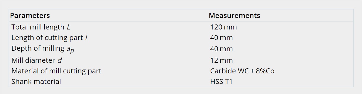
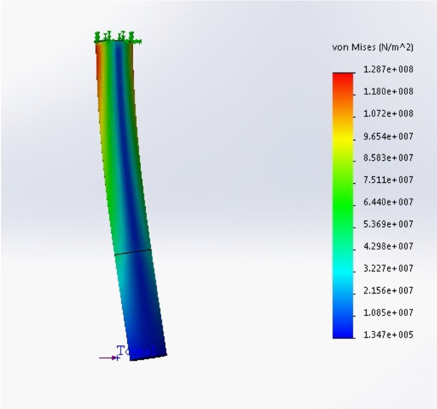
Fig.5 Distribution pattern of strain values in the two-component mill model
.jpg)
Fig.6 Change pattern in the values of deformations (vertical deflections)
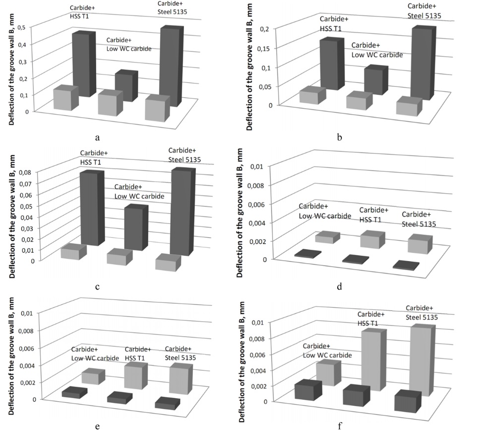
Fig.7 Nomogram of comparisons of accuracy parameters for machining of groove wall ((a, b, c) vc = 200; (d, e, f) 300 m/min, (a, b, c) ap = 40; (d, e, f) 5 mm, (a, b, c) fz = 0.1; (d, e, f) 0.15 mm/tooth)
4.2 Application of two-component mills with nano-scale multilayer composite coatings (NMCC)
As shown in numerous papers, the use of modifying coatings not only can increase the tool life and reliability, but it can also produce a significant influence on parameters of the cutting process, such as cutting forces, as well as temperature and vibrations in the cutting area. In turn, changes in those parameters directly affect the accuracy of machining. Thus, it can be assumed that the use of modifying coatings, in particular, NMCC, will further improve the accuracy parameters of machining with the use of two-component mills. The NMCC Zr-ZrN-(ZrCrAl)N with total thickness of 3 µm was chosen as a modifying coating. The above NMCC was chosen due to the need to provide sufficient hardness in combination with good toughness and crack resistance, and the choice was based on previous studies. The microstructure of NMCC Zr-ZrAlN-(ZrCrAl)N on a transversal cross section is presented in Figure 8. The thickness of the nano-layers is 20–40 nm, and the coating thickness is 3 μm.
The conducted cutting tests (Fig. 9) confirm the above assumption and found that the use of NMCC allows setting the accuracy parameters of machining with the use of two-component mills close to the parameters of machining with monolithic mills and, in some cases (in the use of a shank from low WC carbide), even to exceed those characteristics.
N%20on%20a%20transversal%20cross%20section.jpg)
The conducted cutting tests (Fig. 9) confirm the above assumption and found that the use of NMCC allows setting the accuracy parameters of machining with the use of two-component mills close to the parameters of machining with monolithic mills and, in some cases (in the use of a shank from low WC carbide), even to exceed those characteristics.
Fig. 8 Microstructure of NMCC Zr-ZrAlN-(ZrCrAl)N on a transversal cross section
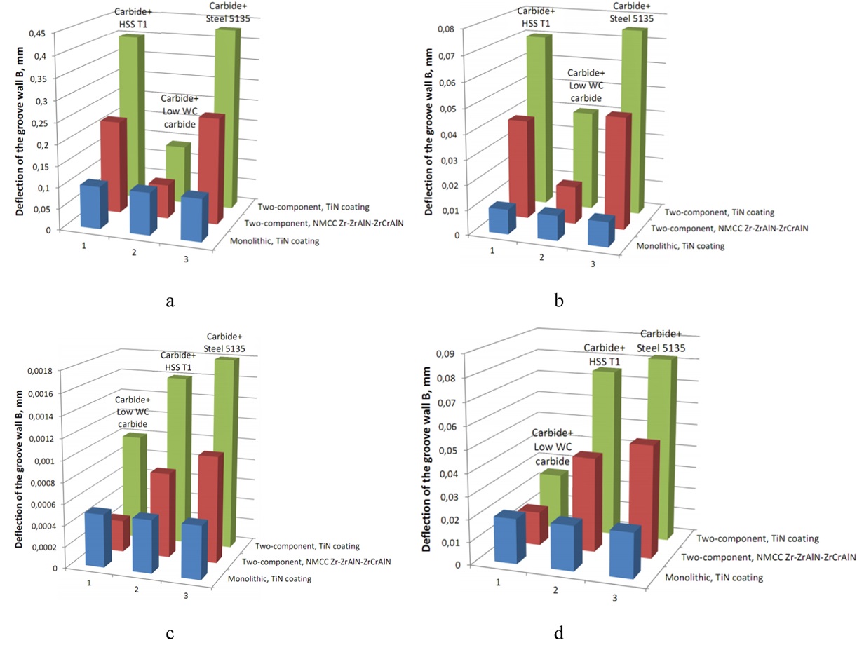
Fig.9 Nomogram of comparisons of accuracy parameters for machining of groove wall (a, b) vc = 200; (c, d) 300 m/min, (a, b) ap = 40; (c, d) 5 mm, (a, b) fz = 0.1; (c, d) 0.15 mm/tooth): (a) groove depth of 40 mm, with a total mill length of 220 mm; (b) groove depth 40 mm, with a total mill length of 90 mm; (c) groove depth of 5 mm, with a total mill length of 90 mm; (d) groove depth of 5 mm, with a total mill length of 220 mm
4.3 Study of nature of end mill wear
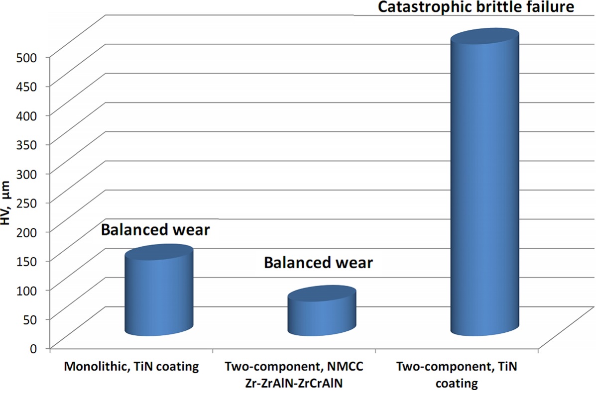
Let us consider the differences in the nature of wear for monolithic and two-component end mills with shanks of low WC carbide with groove depth of 40 mm and a total end mill length of 90 mm (vc = 200 m/min, ap = 40 mm, fz = 0.1 mm/tooth). The comparison of wear values on flank wear land and the nature of wear after 25 min of milling are shown in Figure 10.
Let us consider the nature of wear of an end mill tooth after 25 min of milling with the above mentioned milling parameters. For a two-component end mill with TiN coating, brittle fracture is observed, resulting in catastrophic wear (Fig. 11a and b). This type of wear can be associated with increased vibrations and shock loads arising because of the reduction in rigidity of a two-component end mill. For a monolithic end mill with TiN coating (Fig. 11c and d), the balanced wear is typical, without noticeable flaking. The value of flank wear land is about 130 µm. For a two-component end mill with NMCC Zr-ZrAlN-(ZrCrAl)N (Fig. 11e and f), the balanced nature of wear is typical, without formation of microchips and brittle failure. After 25 min of milling, the end mill showed the lowest value of flank wear land at 59 µm.
Let us consider the nature of wear of an end mill tooth after 25 min of milling with the above mentioned milling parameters. For a two-component end mill with TiN coating, brittle fracture is observed, resulting in catastrophic wear (Fig. 11a and b). This type of wear can be associated with increased vibrations and shock loads arising because of the reduction in rigidity of a two-component end mill. For a monolithic end mill with TiN coating (Fig. 11c and d), the balanced wear is typical, without noticeable flaking. The value of flank wear land is about 130 µm. For a two-component end mill with NMCC Zr-ZrAlN-(ZrCrAl)N (Fig. 11e and f), the balanced nature of wear is typical, without formation of microchips and brittle failure. After 25 min of milling, the end mill showed the lowest value of flank wear land at 59 µm.
Fig. 10 Comparison of wear values on flank wear land and the nature of wear of monolithic and two-component end mills after 25 minutes of milling with groove depth of 40 mm, with a total end mill length of 90 mm (vc = 200 m/min, ap = 40 mm, fz = 0.1 mm/tooth)
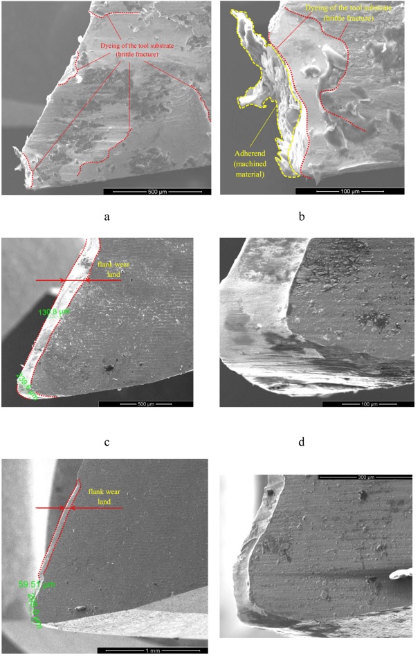
Fig.11 The nature of wear of end mill teeth after 25 minutes of cutting with groove depth of 40 mm and a total end mill length of 90: (a, b) Carbide + steel 5135, TiN coating, (c, d) monolithic, TiN coating, (e, f) Carbide + Low WC carbide, NMCC Zr-ZrAlN-(ZrCrAl)N
5. Conclusion
Various aspects of the application of two-component end mills as alternatives to monolithic end mills have been considered. It is shown that, under certain machining conditions (relatively short end mill length and depth of milling), two-component mills are quite comparable with monolithic end mills in terms of accuracy of machining. The use of multilayer composite nano-structured coatings, in particular, Zr-ZrAlN-(ZrCrAl)N, makes it possible to further increase the accuracy of machining due to the reduction of cutting forces, temperature, and vibrations in the cutting area. The use of two-component end mills is advisable when machining workpieces made of materials with good machinability. When machining hard-to-cut materials, in particular, aluminum-lithium alloys, two-component end mills with multilayer composite nano-structured coatings can also be an alternative to monolithic end mills.
The application of SolidWorks software for simulation of the FEM allowed us to obtain the spatial patterns of strains in an end mill body and the value of corresponding deformations in its various sections.
Based on the results of the research, the following conclusions can also be drawn:
• shank material should be characterized by high resistance to cyclic fatigue failure and ability to maintain lower hardness compared with the material of the cutting part;
• deformations of two-component end mills are slightly higher than those of solid end mills; however, in general, they satisfy the accuracy parameters of workpieces of general mechanical-engineering industry and non-contiguous surfaces of workpieces of aircraft and ship components;
• use of special multilayer composite nano-structured coatings allows ensuring the balanced nature of wear of end mills with the significant increase in their wear resistance.
Thus, the use of two-component end mills with multilayer composite nano-structured coatings can allow reducing the cost of machining (by reducing the cost of the end mill by 20% to 25%) while maintaining or even increasing the tool life (at 30% to 50% compared to the monolithic end mill with a commercial coating) and accuracy parameters of machining.
Acknowledgments
This research was financed by the Ministry of Education and Science of the Russian Federation in the framework of the state order in the sphere of scientific activity (Leading researchers, project 16.9575.2017/6.7).