Techniques of Intelligent Manufacturing for Difficult-to-cut Material Applied in Components of Aerospace Industry
2020-03-31
Titanium alloys and nickel-base super alloys are widely in the manufacture of components for aircraft turbine engines because of their ability to retain high strength at elevated temperatures. Because of its high strength, poor thermal diffusion and work hardening, the cutting of these alloys results in the life of tools and efficiency of works for the worse. So the encountered great difficulties in machining difficult-to-cut materials must be solved. To development and application of key technologies be quickly, and create new cutting technology, so as to meet the demand of aerospace industry. The paper will use the development and manufacture of aerospace components with difficult-to-cut material as examples to introduce five-axis machining, hybrid process, rotary ultrasonic-assisted machining process, and on-line measurement basic technique. The research and development of the intelligent manufacturing technologies for aerospace industry also be discussion.
The aviation industry has always been equipped with stringent quality system certification and highly complex integration technologies, and the aviation industry has been used as an indicator of the technical capabilities of national industries around the world. According to Boeing's Commercial Market Outlook, air transportation will grow at an average annual rate of 4.7% over the next 20 years (2018-2037), generating business opportunities in the aviation manufacturing industry. As a result, global demand for new passenger aircraft is estimated to be around 42,000 over the next 20 years, with a market value of US$6.3 trillion, with the Asia-Pacific region seeing the strongest demand for new aircraft. With the promotion and guidance of the relevant units of the Ministry of Economic Affairs, China's aviation industry has established a supply chain system for related civil aviation products and established partnerships with world-renowned airline manufacturers such as Boeing, Airbus, Bombardier, Kiwi, Pratt & Whitney and Snecma. The total output value of China's aviation industry was NT$120.725 billion in FY2018, up about 11.27% from the previous year (Figure 1). Since 2016, the government has been promoting the national production of national aircraft, the production of high-class trainer aircraft, and subsequent military aircraft, making the aviation industry a bright spot for development. The aviation industry has been booming lately, and the industry is in great demand for talent. In the past two years, thousands of jobs will be created in the industry, making it an extremely competitive industry (1,2).
.jpg)
The Ministry of Economic Affairs (MOEA) has identified the aviation industry as a key project to promote the high value-addedness of the industry in the light of the status and future development trend of the domestic aviation industry, and has planned four major strategies: "upgrading the international supply chain", "developing niche aviation system components", "exploring the Asia-Pacific market and global expansion" and "developing high value-added products and application services using aviation technology". In the future, we will continue to introduce aviation-grade technology to further promote the transformation of traditional domestic industries into the aviation industry, expand the scale of the industry, promote the high value-addedness of the aviation industry and make it a core industry for stabilizing national export earnings.
According to the cost of aircraft components, the engine accounts for about 27% of them, which is only less than 38% of the fuselage, and the countries in the world that can fully independently develop advanced aircraft engines are limited to the United States, Britain, France, Russia and other countries. In terms of driving principle, there are three main types of aviation engines: turbofan, turbopro and turboshaft, which are used in jet, propeller and helicopter aircraft. The turbofan engine is currently the largest in the aircraft market due to its high efficiency, low noise, small size and high reliability design. The Boeing 757 turbofan engine includes the following non-ferrous metals and alloys: titanium 38%, nickel-based alloys 37%, chromium 12%, cobalt 6%, aluminum 5%, niobium 1%, tantalum 0.02%. Without these materials, the jet engine would not be able to operate under the required conditions and kinetic energy (as shown in Figure 2).
.jpg)
Titanium alloys (α - type, α + β - type, β - type) have excellent strength to density ratios and corrosion resistance. They are also widely used in the aerospace industry and daily life due to their light weight, corrosion resistance, high temperature resistance, high fatigue strength, low thermal expansion coefficient, non-magnetic, and non-toxic metal materials. However, due to the physical properties of titanium alloys, such as high strength, difficulty in milling, susceptibility to milling chatter, high milling temperature due to low thermal conductivity and low coefficient of thermal expansion, and the high temperature generated during machining, the chemically reactive titanium alloys react with the aerospace end mill material, resulting in wear and tear of the aerospace end mill, which affects the life of the aerospace end mill (high chemical affinity), etc. (3) (Figure 3(a)).
Titanium alloy is not only used in the aerospace industry, vehicles, and sports equipment industries, but also in the emerging medical industry, such as the processing and production of bone nails and plates for medical implants and the production of artificial tooth roots. In particular, the current trend of titanium alloy is increasing day by day, as the material is defined as a difficult material to cut and therefore there is an urgent need for its milling parameters, in order to find the best possible factors and levels for this milling process. When milling titanium and titanium alloy, it is advisable to use straight milling, preferably with a small diameter milling cutter with a large number of teeth, which can reduce vibration. If machining is difficult, the front angle should be reduced by 0 degrees or be negative. For milling, it is important to choose the right lubricating coolant. It is generally advisable to use a water-soluble lubricating coolant, which should be added by spraying it in a spray form.
High-temperature alloys can be divided into four types: iron-based, iron-nickel-based, nickel-based and cobalt-based, among which the nickel-based superalloys contain more than 50% nickel and the working temperature can reach 1000 °C. Through the solid solution and aging method to strengthen, it can obtain better strength and heat resistance, so it is widely used in aviation engines. Iron-based high-temperature alloys are iron-based and are suitable for parts with lower operating temperatures. Iron-nickel-based high-temperature alloys with a nickel content of 30%-40% have a higher tensile strength than nickel-based and cobalt-based alloys and are suitable for slightly higher operating temperatures than iron-based alloys. The cobalt-based high-temperature alloys are based on cobalt, which accounts for about 45%-60%, and Cr, Ni, C, W, Mo, Fe, etc. are added to improve the heat resistance.
Inconel 718 nickel-based superalloys (50%-55% nickel) are widely used in high temperature, high load, and corrosion resistant environments due to their good mechanical strength, fatigue limit, and high temperature corrosion resistance at high temperatures (700 °C) (3) (Figure 3(b)). However, the low thermal conductivity and specific heat value of Inconel 718 nickel-based superalloys, and their good mechanical properties at high temperatures, make this material a high milling force and slow heat dissipation during milling operations, resulting in high mill temperatures. The build-up edge of chips and cutters can easily occur when milling nickel-based superalloys. In addition, Inconel 718 nickel-based superalloys have a Vospertane-type base with a higher Nb content than other alloys, which can easily precipitate a hard γ" (Ni3Nb) secondary phase, resulting in machining hardening during milling. Make the milling cutter wear out quickly.
.jpg)
The application of difficult-to-cut materials for aerospace components is the example of impellers, one of the most important and novel components of modern aviation engines, first used in the small engines of helicopters. In the 1980s, it was used in military aircraft engines and was rapidly adopted by commercial turbine fans and turboprop aircraft. Its advantages include: (1) Lightweight (typically 20-30% weight loss): due to the use of fewer leaves. (2) The root of the leaf is integrated with the disc. (3) Higher aerodynamic efficiency. (4) To enhance the service life, the fatigue strength will not be affected by corrosion of the joints and parts. However, BLISK also has its disadvantages, mainly the difficulty of machining (complex torsional surfaces and difficult-to-cut materials) and the high price of its manufacture and restoration. And to ensure its reliability, strict quality control is a necessary manufacturing process. The structure of the compressor impellers of common aircraft engines and industrial gas turbines is such that individual blades are positioned on the discs in a welded or locked fashion. BLISKs are also known as integrated bladed rotors (IBR), meaning that the blade root geometry and positioning slots are no longer needed and the disc rotors and blades are integrated (as shown in Figure 4) (4). Martin Busmann, Dr. Erwin Bayer (5), illustrates the current status of integrated bladed compressors and BLISK manufacturing technology development in today's engine structures, and the future challenges of applying technology to BLISK manufacturing to meet functionality, quality and cost. The article also introduces two important design and manufacturing methods to achieve weight reduction, one is to weld individual BLISKs into multi-stage BLISK drums; the other is hollow fan blade technology. The manufacturing feasibility of the dual-material BLISK is being developed for application in the high-stress turbine segment. In addition, the design of BLISK needs to take into account the technology and methods of future restoration.
Free-form surfaces, also known as sculptured surfaces, have been widely used in modern engineering to replace lefting surfaces, such as automotive sheet metal molds, injection molds, turbine blades, marine propellers and aerospace components. For performance reasons, these products are characterized by complex three-dimensional curved surfaces. If they are machined with a conventional three-axis tooling machine, the disadvantages of poor efficiency and accuracy must be overcome. These limitations due to the freedom of the tooling machine and the choice of milling cutters can be overcome with 5-axis machining.
Theoretically multi-axis machining has far more manufacturing advantages than conventional three-axis machining, including higher productivity and better quality of machining (6). However, there are also many drawbacks to multi-axis machining in practice, most of these drawbacks are related to the complexity of aerospace end mill synchronicity in multi-axis tooling machines, the interference (interference) between the aerospace end mill and the surface, and collision (7). These problems include inadequate support by conventional CAD/CAM systems; difficulty in overcutting and collision detection algorithms between milling cutters and adjacent surfaces (8); more stringent dynamic accuracy of the machine due to the complex structure of the multi-axis tooling machine (9); more complex design of the tooling machine controller for multi-axis NC data processing, so that the milling cutter path is processed by an interpolator to ensure machining accuracy (10).
Current commercial CAD/CAM software with multi-axis machining capabilities is still expensive and inflexible in specifying end mill orientation and end mill path distribution for complex surface machining, which generally requires multiple attempts to succeed (11). Traditionally the orientation of the milling cutter is usually kept constant during machining, e.g. during the movement of the milling cutter, the orientation of the milling cutter deviates from the normal vector of the surface at a certain angle, ranging from approximately. Although this method is more efficient than machining with 3-axis ball cutters, the problem of overcutting still exists and the residue left on the surface has to be removed by manual grinding. These problems will become more serious as the surface becomes more complex.
The freedom provided by the multi-axis tooling machine has the advantages of avoiding interference, reducing repeated positioning errors, and reducing the cost of fixtures. For hard-to-cut materials (titanium alloys, nickel-based superalloys), based on the complex curved surfaces and geometric features of precision components, we establish manufacturing procedures (positioning machining and multi-axis simultaneous machining mode), consider milling vibrations and machining modes, and plan and design corresponding clamps and tooling machines. Aided by online milling force analysis, planning of milling force paths. The advantage of this method is that equal volume milling extends the life of the end mill and reduces the roughing time by increasing the cutting depth. The impeller surface finishing mode, including point contact milling and side edge milling techniques, is selected based on the degree of surface torsion and surface tolerance. If the curvature of a surface varies more smoothly, then side edge milling is far superior to point contact milling due to milling efficiency considerations. Fig. 5 is a flowchart of the 5-axis CNC machining program of the Aero-Superior Gold Impeller. Figure 6 shows a process system flow analysis using a titanium alloy impeller as an example.
Generally speaking, the post-processing program converts aerospace end mill position data into the data needed for machining operations, such as program home position setting, machine home position setting, spindle speed, aerospace end mill feed, aerospace end mill coordinates control point. Since tool machine controller manufacturers often fail to follow international standards in defining control codes, resulting in post-processing conversions having to define relevant control codes based on various types of controllers, and if the factory has multiple tool machines with different controllers, different post-processing must be prepared for conversion, making post-processing more important (12).
.jpg)
.jpg)
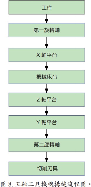
Since the construction of the tool machine is a kinematics chain consisting of a combination of individual rod connectors, the connectors are nothing more than sliding or rotating pairs. Therefore, the kinematic chain of motion relationship effectively describes the trajectory of the milling cutter of a tooling machine in space, derives the geometric range of motion of the milling cutter from the tooling machine, and thus determines the main function of the tooling machine, which is the concept of tooling machine shape creation function proposed by Reshetov and Portman (13). The derivation of the post-processing program is based on the concept of the shape of the five-axis machine to create a matrix of functions, which in turn is used to solve the equations of the axes of the control machine by reverse kinematics. Therefore, the limitation and post-processing of multi-axis tool machine connectors is based on the principles of forward and reverse kinematics. Apply the flush coordinate conversion matrix to describe the relative position relationship (forward kinematics) between the axes and the milling cutter of a multi-axis tooling machine, and then make this matrix equal to the planned milling cutter position matrix.
In order to avoid interference between the path of the 5-axis milling cutter and the surface, it must be verified by physical milling simulation, which in general CAM software is based on reading the cutter position file and not knowing if there is interference collision. The NC programmed milling simulation is also required to accurately determine whether the five-axis aerospace end millpaths created can meet the machining tolerances. Therefore, in this paper, the same five-axis virtual tooling machine as the actual milling test is created in the milling simulation software. The machine is configured as an inclined rotary table and a swing-head rotary table.
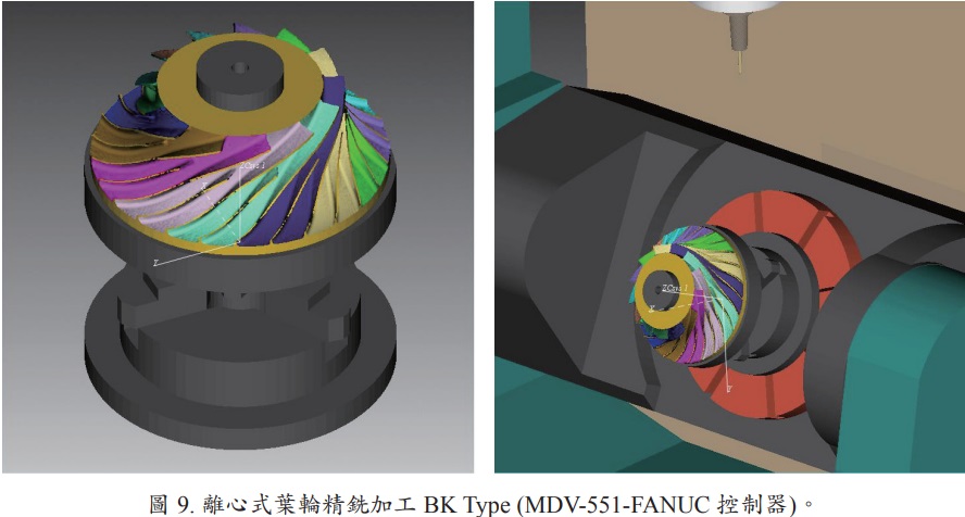
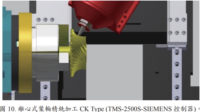
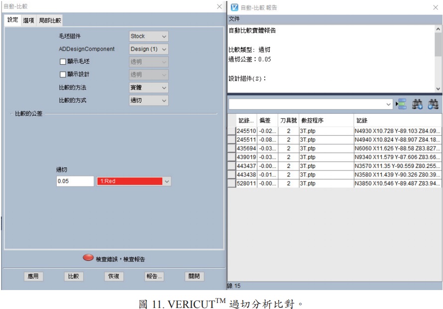
Using titanium alloy centrifugal impeller as an example, virtual manufacturing and error analysis is performed with the aid of physical milling simulation software to confirm the correct path of the end mill on the one hand, so as to avoid the collision of the end mill, workpiece, fixture, and machine, as shown in Figures 9 to 10. On the other hand, due to tolerance requirements, it is necessary to verify that the planned machining process and the chord differences and spacing set to the path of the resulting aerospace end mill meet the requirements. As shown in FIGS. 11 to 12. By means of an error comparison analysis, the aerospace end mill path can be further adjusted to set the conditions.
The energy consumption, cost and materials required for this process are only part of the new product. The remanufacturing of common mechanical components relies on skilled technicians and a series of labor-intensive operations, often requiring the remanufacturer to travel back and forth with an outsourced contractor. This form of remanufacturing is difficult for high-value components (turbine blades, BLISK) that require strict quality control and production time considerations. In the restoration process, the basis for automated equipment using high-speed metal removal processes (milling or grinding), in-line scanning and inspection technology, and laser cladding/welding has been established, but has not yet been integrated to the stage of commercial availability. With the development of this CNC equipment, the grinding, melting, milling, grinding and polishing of the impeller before melting is gradually replaced by the tool machine. The latest technological developments include: (1) arranging the relevant processes and inspections in the same manufacturing unit and linking them via a robotic arm; (2) integrating these processes into a single tooling machine to form an intelligent and complex CNC tooling machine (milling + inspection + laser cladding + inspection + laser heat treatment).
A joint team of eight UK-based units(14) (Delcam, Renishaw, Electrox, TWI, Precision Engineering Technologies, Cummins Turbo Technologies, Airfoils Technology International, De Montfort University) has developed a fully integrated production system and software for the repair of high-value components with minimal human intervention based on cost, fast and reliable remanufacturing applications. The scheme, known as RECLAIM (Manufacture of high value products using a Combined LAser cladding, Inspection and Machining system), will put the UK ahead of other countries in terms of remanufacturing technology. This single platform includes: (1) high speed scanning modules; (2) fast laser fusion cladding; (3) high efficiency machining; (4) adaptive CAD/CAM systems; (5) system automation; (6) workflow management. This new system focuses on the repair of damaged components, the manufacture of new metal components, the renewal of obsolete parts, and the renewal of standard parts.Jason Jones et al. (15), explore the research and development of RECLAIM. In the case of aerospace turbine blade repair, which includes component alignment, defect identification, defect removal, defect repair, and finishing, the system is inherently designed to be as flexible as possible to face the maximum number of variables that exist in the reproduction environment. For turbine blades, BLISK and other high-value components, the use of AM/cladding technology can save time and cost in the process of manufacturing and repairing new products.
Advanced materials such as hard and brittle materials (ceramics, zirconia, sapphires, glass, silicon wafers) and composites have their superior properties respectively, and thus engineering applications (semiconductors, optoelectronics, aerospace, medical devices, energy, electric vehicles, 3C electronics, precision machinery) are becoming more widespread. However, it is difficult to form or process such tough and high temperature resistant advanced materials to the correct size and geometry, and the current technology and techniques require higher processing costs and time, which limits their application. Therefore, it is important to develop a reliable and cost-effective manufacturing process for these advanced materials. Rotary ultrasonic machining (RUM) is relatively inexpensive compared to current non-traditional machining processes, environmentally friendly and suitable for the foundation requirements of traditional machining environments.
It combines the material removal mechanism of diamond tools with ultrasonic machining (USM), which combines the dual motion of high frequency vibration and high speed rotation of axial aerospace end mills to form a combined abrasive and impact-damaging material processing technique that can easily process high hardness and brittle materials. In rotary ultrasound-assisted milling applications, including drilling, milling, and polishing processes, machining efficiency, tool wear life, and surface finish are key considerations. In the area of rotary ultrasonic assisted milling, the research focuses on the relationship between material removal rate and process parameters, including amplitude, static force, speed, number of abrasive grains, and abrasive diameter (18); in the area of polishing, the research focuses on the surface processing of sapphire brittle materials. Fig. 16 shows the rotary ultrasound-assisted 5-axis machine of this department, Fig. 17 for microporous machining, and Figs. 18 to 19 for artificial crown (titanium alloy, medical ceramic) complex surface machining.
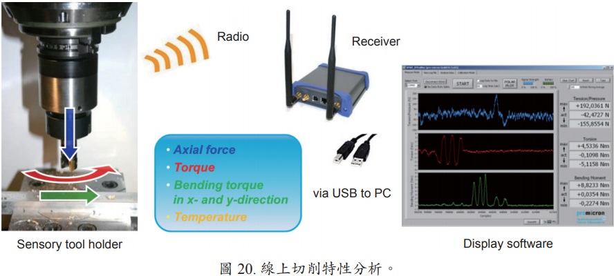
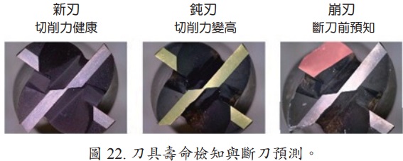
Based on the need for research on hard-to-cut material process milling models, cloudization of processing data, intelligent operation of collaborative tooling machines, and tool life detection and tool breaking prediction, the axial forces, torques, bending moments in X-Y direction, and temperatures during the milling process are measured and exported to a computer in real time through a toolholder with sensors for tool life evaluation, tool design development, process improvement, and productivity enhancement. The information on milling characteristics collected by evaluating actual milling tests can be used as a reference for selecting milling cutters for milling machining and for planning the path of the cutter (equal milling force). The end mill life detection and tool breaking prediction are shown in Figure 22.
Bending moments and temperatures in the direction of the end mill are measured and exported to a computer in real time for tool life evaluation, end mill design development, process improvement, and increased productivity. The information on milling characteristics collected by evaluating the actual milling test can be used as a reference for selecting milling cutters for milling machining and for planning the path of the cutter (equal milling force). The end mill life detection and tool breaking prediction are shown in Figure 22.
In-process measurement refers to the measurement of a surface when the surface milling is completed, and the tooling machine's milling cutter is replaced with a probe (probe). In the field of manufacturing integration system, the integration of numerical control tool machine milling with online measurement and CAD/CAM system can achieve the goal of process systematization and computerization, enhancing the image and competitiveness of the industry. Important considerations in online measurement include setting the orientation of the workpiece, measurement procedures and path planning, collision assessment, error estimation, and error compensation and correction (19, 20).
To reduce scrap, reduce machine downtime, increase productivity, and provide flexibility for a wide variety of small-scale production, the tool probe can be used to identify components to select the correct NC program, locate reference features to establish a workpiece coordinate system, check part size to confirm machining balance and rough milling procedures, and measure part orientation (relative to machine axis) to perform coordinate rotation. In addition, using the aerospace end mill setter, you can measure the cutter length to establish the cutter diameter correction and check that the cutter length is within the set tolerance and measure the diameter of the aerospace end mill in rotation to establish the cutter diameter correction value.
For in-process monitoring, Productivity+TM Active Editor Pro tool probe software is used to plan the measurement paths. The purpose is to confirm the amount of allowance after machining and the accuracy of the surface after finishing, and to assess whether the aerospace end mill paths should be compensated to improve machining accuracy and process efficiency. To avoid programming errors or interference with surfaces, the measurement path must be verified by virtual machine path simulation before actual machine measurements are made. Figure 23 shows the intelligent automated process control technology for turbine blade manufacturing, which integrates geometric modeling, 5-axis machining, and online and offline geometric measurement techniques.
In the future, advanced materials that are lightweight, tougher and more resistant to high temperatures will be widely used. The combination of a 5-axis machine and a compounding machine will maximize the range and type of machining possible on a single machine. It is also because five-axis CNC machining technology is very helpful to the manufacturing of high value precision parts such as aerospace parts in terms of product accuracy and cost efficiency.
Through the integration of CAD/CAM system, virtual reality integration technology, composite process technology and intelligent automated process control technology, the development of process technology for hard-to-cut aerospace parts can not only ensure product accuracy and delivery time, but also collect and analyze the real-time production information of each production equipment and online milling load to provide the most suitable manufacturing conditions and discover the root causes of abnormalities, which will be more efficient and competitive in production.
I. Background
The aviation industry has always been equipped with stringent quality system certification and highly complex integration technologies, and the aviation industry has been used as an indicator of the technical capabilities of national industries around the world. According to Boeing's Commercial Market Outlook, air transportation will grow at an average annual rate of 4.7% over the next 20 years (2018-2037), generating business opportunities in the aviation manufacturing industry. As a result, global demand for new passenger aircraft is estimated to be around 42,000 over the next 20 years, with a market value of US$6.3 trillion, with the Asia-Pacific region seeing the strongest demand for new aircraft. With the promotion and guidance of the relevant units of the Ministry of Economic Affairs, China's aviation industry has established a supply chain system for related civil aviation products and established partnerships with world-renowned airline manufacturers such as Boeing, Airbus, Bombardier, Kiwi, Pratt & Whitney and Snecma. The total output value of China's aviation industry was NT$120.725 billion in FY2018, up about 11.27% from the previous year (Figure 1). Since 2016, the government has been promoting the national production of national aircraft, the production of high-class trainer aircraft, and subsequent military aircraft, making the aviation industry a bright spot for development. The aviation industry has been booming lately, and the industry is in great demand for talent. In the past two years, thousands of jobs will be created in the industry, making it an extremely competitive industry (1,2).
The Ministry of Economic Affairs (MOEA) has identified the aviation industry as a key project to promote the high value-addedness of the industry in the light of the status and future development trend of the domestic aviation industry, and has planned four major strategies: "upgrading the international supply chain", "developing niche aviation system components", "exploring the Asia-Pacific market and global expansion" and "developing high value-added products and application services using aviation technology". In the future, we will continue to introduce aviation-grade technology to further promote the transformation of traditional domestic industries into the aviation industry, expand the scale of the industry, promote the high value-addedness of the aviation industry and make it a core industry for stabilizing national export earnings.
According to the cost of aircraft components, the engine accounts for about 27% of them, which is only less than 38% of the fuselage, and the countries in the world that can fully independently develop advanced aircraft engines are limited to the United States, Britain, France, Russia and other countries. In terms of driving principle, there are three main types of aviation engines: turbofan, turbopro and turboshaft, which are used in jet, propeller and helicopter aircraft. The turbofan engine is currently the largest in the aircraft market due to its high efficiency, low noise, small size and high reliability design. The Boeing 757 turbofan engine includes the following non-ferrous metals and alloys: titanium 38%, nickel-based alloys 37%, chromium 12%, cobalt 6%, aluminum 5%, niobium 1%, tantalum 0.02%. Without these materials, the jet engine would not be able to operate under the required conditions and kinetic energy (as shown in Figure 2).
Titanium alloys (α - type, α + β - type, β - type) have excellent strength to density ratios and corrosion resistance. They are also widely used in the aerospace industry and daily life due to their light weight, corrosion resistance, high temperature resistance, high fatigue strength, low thermal expansion coefficient, non-magnetic, and non-toxic metal materials. However, due to the physical properties of titanium alloys, such as high strength, difficulty in milling, susceptibility to milling chatter, high milling temperature due to low thermal conductivity and low coefficient of thermal expansion, and the high temperature generated during machining, the chemically reactive titanium alloys react with the aerospace end mill material, resulting in wear and tear of the aerospace end mill, which affects the life of the aerospace end mill (high chemical affinity), etc. (3) (Figure 3(a)).
Titanium alloy is not only used in the aerospace industry, vehicles, and sports equipment industries, but also in the emerging medical industry, such as the processing and production of bone nails and plates for medical implants and the production of artificial tooth roots. In particular, the current trend of titanium alloy is increasing day by day, as the material is defined as a difficult material to cut and therefore there is an urgent need for its milling parameters, in order to find the best possible factors and levels for this milling process. When milling titanium and titanium alloy, it is advisable to use straight milling, preferably with a small diameter milling cutter with a large number of teeth, which can reduce vibration. If machining is difficult, the front angle should be reduced by 0 degrees or be negative. For milling, it is important to choose the right lubricating coolant. It is generally advisable to use a water-soluble lubricating coolant, which should be added by spraying it in a spray form.
High-temperature alloys can be divided into four types: iron-based, iron-nickel-based, nickel-based and cobalt-based, among which the nickel-based superalloys contain more than 50% nickel and the working temperature can reach 1000 °C. Through the solid solution and aging method to strengthen, it can obtain better strength and heat resistance, so it is widely used in aviation engines. Iron-based high-temperature alloys are iron-based and are suitable for parts with lower operating temperatures. Iron-nickel-based high-temperature alloys with a nickel content of 30%-40% have a higher tensile strength than nickel-based and cobalt-based alloys and are suitable for slightly higher operating temperatures than iron-based alloys. The cobalt-based high-temperature alloys are based on cobalt, which accounts for about 45%-60%, and Cr, Ni, C, W, Mo, Fe, etc. are added to improve the heat resistance.
Inconel 718 nickel-based superalloys (50%-55% nickel) are widely used in high temperature, high load, and corrosion resistant environments due to their good mechanical strength, fatigue limit, and high temperature corrosion resistance at high temperatures (700 °C) (3) (Figure 3(b)). However, the low thermal conductivity and specific heat value of Inconel 718 nickel-based superalloys, and their good mechanical properties at high temperatures, make this material a high milling force and slow heat dissipation during milling operations, resulting in high mill temperatures. The build-up edge of chips and cutters can easily occur when milling nickel-based superalloys. In addition, Inconel 718 nickel-based superalloys have a Vospertane-type base with a higher Nb content than other alloys, which can easily precipitate a hard γ" (Ni3Nb) secondary phase, resulting in machining hardening during milling. Make the milling cutter wear out quickly.
The application of difficult-to-cut materials for aerospace components is the example of impellers, one of the most important and novel components of modern aviation engines, first used in the small engines of helicopters. In the 1980s, it was used in military aircraft engines and was rapidly adopted by commercial turbine fans and turboprop aircraft. Its advantages include: (1) Lightweight (typically 20-30% weight loss): due to the use of fewer leaves. (2) The root of the leaf is integrated with the disc. (3) Higher aerodynamic efficiency. (4) To enhance the service life, the fatigue strength will not be affected by corrosion of the joints and parts. However, BLISK also has its disadvantages, mainly the difficulty of machining (complex torsional surfaces and difficult-to-cut materials) and the high price of its manufacture and restoration. And to ensure its reliability, strict quality control is a necessary manufacturing process. The structure of the compressor impellers of common aircraft engines and industrial gas turbines is such that individual blades are positioned on the discs in a welded or locked fashion. BLISKs are also known as integrated bladed rotors (IBR), meaning that the blade root geometry and positioning slots are no longer needed and the disc rotors and blades are integrated (as shown in Figure 4) (4). Martin Busmann, Dr. Erwin Bayer (5), illustrates the current status of integrated bladed compressors and BLISK manufacturing technology development in today's engine structures, and the future challenges of applying technology to BLISK manufacturing to meet functionality, quality and cost. The article also introduces two important design and manufacturing methods to achieve weight reduction, one is to weld individual BLISKs into multi-stage BLISK drums; the other is hollow fan blade technology. The manufacturing feasibility of the dual-material BLISK is being developed for application in the high-stress turbine segment. In addition, the design of BLISK needs to take into account the technology and methods of future restoration.
.jpg)
II. Five-axis machining technology in the development of aerospace component manufacturing process
Free-form surfaces, also known as sculptured surfaces, have been widely used in modern engineering to replace lefting surfaces, such as automotive sheet metal molds, injection molds, turbine blades, marine propellers and aerospace components. For performance reasons, these products are characterized by complex three-dimensional curved surfaces. If they are machined with a conventional three-axis tooling machine, the disadvantages of poor efficiency and accuracy must be overcome. These limitations due to the freedom of the tooling machine and the choice of milling cutters can be overcome with 5-axis machining.
Theoretically multi-axis machining has far more manufacturing advantages than conventional three-axis machining, including higher productivity and better quality of machining (6). However, there are also many drawbacks to multi-axis machining in practice, most of these drawbacks are related to the complexity of aerospace end mill synchronicity in multi-axis tooling machines, the interference (interference) between the aerospace end mill and the surface, and collision (7). These problems include inadequate support by conventional CAD/CAM systems; difficulty in overcutting and collision detection algorithms between milling cutters and adjacent surfaces (8); more stringent dynamic accuracy of the machine due to the complex structure of the multi-axis tooling machine (9); more complex design of the tooling machine controller for multi-axis NC data processing, so that the milling cutter path is processed by an interpolator to ensure machining accuracy (10).
Current commercial CAD/CAM software with multi-axis machining capabilities is still expensive and inflexible in specifying end mill orientation and end mill path distribution for complex surface machining, which generally requires multiple attempts to succeed (11). Traditionally the orientation of the milling cutter is usually kept constant during machining, e.g. during the movement of the milling cutter, the orientation of the milling cutter deviates from the normal vector of the surface at a certain angle, ranging from approximately. Although this method is more efficient than machining with 3-axis ball cutters, the problem of overcutting still exists and the residue left on the surface has to be removed by manual grinding. These problems will become more serious as the surface becomes more complex.
1. Planning of milling process
The freedom provided by the multi-axis tooling machine has the advantages of avoiding interference, reducing repeated positioning errors, and reducing the cost of fixtures. For hard-to-cut materials (titanium alloys, nickel-based superalloys), based on the complex curved surfaces and geometric features of precision components, we establish manufacturing procedures (positioning machining and multi-axis simultaneous machining mode), consider milling vibrations and machining modes, and plan and design corresponding clamps and tooling machines. Aided by online milling force analysis, planning of milling force paths. The advantage of this method is that equal volume milling extends the life of the end mill and reduces the roughing time by increasing the cutting depth. The impeller surface finishing mode, including point contact milling and side edge milling techniques, is selected based on the degree of surface torsion and surface tolerance. If the curvature of a surface varies more smoothly, then side edge milling is far superior to point contact milling due to milling efficiency considerations. Fig. 5 is a flowchart of the 5-axis CNC machining program of the Aero-Superior Gold Impeller. Figure 6 shows a process system flow analysis using a titanium alloy impeller as an example.
2.Five-axis machine tool post-processing program development technology
Generally speaking, the post-processing program converts aerospace end mill position data into the data needed for machining operations, such as program home position setting, machine home position setting, spindle speed, aerospace end mill feed, aerospace end mill coordinates control point. Since tool machine controller manufacturers often fail to follow international standards in defining control codes, resulting in post-processing conversions having to define relevant control codes based on various types of controllers, and if the factory has multiple tool machines with different controllers, different post-processing must be prepared for conversion, making post-processing more important (12).Since the construction of the tool machine is a kinematics chain consisting of a combination of individual rod connectors, the connectors are nothing more than sliding or rotating pairs. Therefore, the kinematic chain of motion relationship effectively describes the trajectory of the milling cutter of a tooling machine in space, derives the geometric range of motion of the milling cutter from the tooling machine, and thus determines the main function of the tooling machine, which is the concept of tooling machine shape creation function proposed by Reshetov and Portman (13). The derivation of the post-processing program is based on the concept of the shape of the five-axis machine to create a matrix of functions, which in turn is used to solve the equations of the axes of the control machine by reverse kinematics. Therefore, the limitation and post-processing of multi-axis tool machine connectors is based on the principles of forward and reverse kinematics. Apply the flush coordinate conversion matrix to describe the relative position relationship (forward kinematics) between the axes and the milling cutter of a multi-axis tooling machine, and then make this matrix equal to the planned milling cutter position matrix.
.jpg)
3. Physical milling verification and virtual error analysis
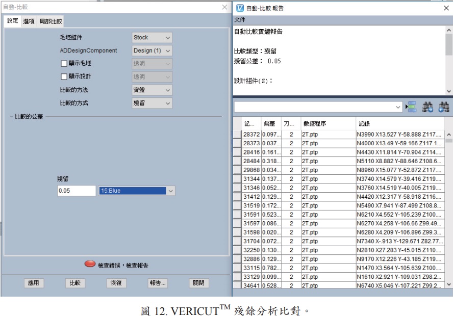
In order to avoid interference between the path of the 5-axis milling cutter and the surface, it must be verified by physical milling simulation, which in general CAM software is based on reading the cutter position file and not knowing if there is interference collision. The NC programmed milling simulation is also required to accurately determine whether the five-axis aerospace end millpaths created can meet the machining tolerances. Therefore, in this paper, the same five-axis virtual tooling machine as the actual milling test is created in the milling simulation software. The machine is configured as an inclined rotary table and a swing-head rotary table.Using titanium alloy centrifugal impeller as an example, virtual manufacturing and error analysis is performed with the aid of physical milling simulation software to confirm the correct path of the end mill on the one hand, so as to avoid the collision of the end mill, workpiece, fixture, and machine, as shown in Figures 9 to 10. On the other hand, due to tolerance requirements, it is necessary to verify that the planned machining process and the chord differences and spacing set to the path of the resulting aerospace end mill meet the requirements. As shown in FIGS. 11 to 12. By means of an error comparison analysis, the aerospace end mill path can be further adjusted to set the conditions.
Ⅲ. Multi-Axis Add-Drop Composite Process Technology (CNC + 3D printing)
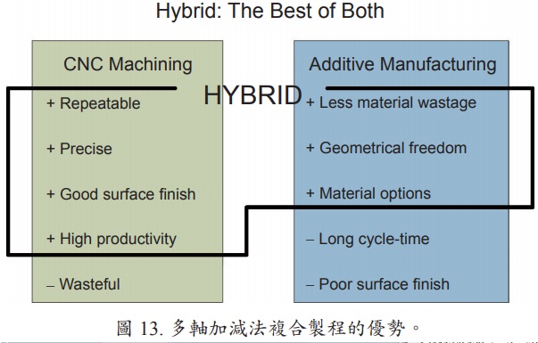
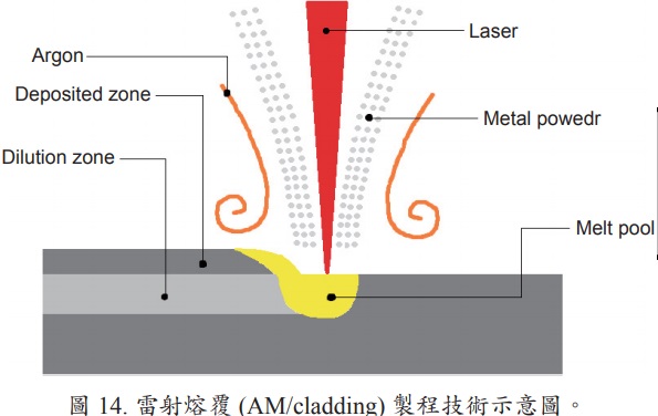
The energy consumption, cost and materials required for this process are only part of the new product. The remanufacturing of common mechanical components relies on skilled technicians and a series of labor-intensive operations, often requiring the remanufacturer to travel back and forth with an outsourced contractor. This form of remanufacturing is difficult for high-value components (turbine blades, BLISK) that require strict quality control and production time considerations. In the restoration process, the basis for automated equipment using high-speed metal removal processes (milling or grinding), in-line scanning and inspection technology, and laser cladding/welding has been established, but has not yet been integrated to the stage of commercial availability. With the development of this CNC equipment, the grinding, melting, milling, grinding and polishing of the impeller before melting is gradually replaced by the tool machine. The latest technological developments include: (1) arranging the relevant processes and inspections in the same manufacturing unit and linking them via a robotic arm; (2) integrating these processes into a single tooling machine to form an intelligent and complex CNC tooling machine (milling + inspection + laser cladding + inspection + laser heat treatment).
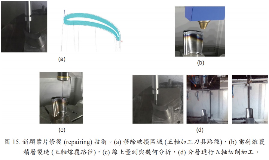
A joint team of eight UK-based units(14) (Delcam, Renishaw, Electrox, TWI, Precision Engineering Technologies, Cummins Turbo Technologies, Airfoils Technology International, De Montfort University) has developed a fully integrated production system and software for the repair of high-value components with minimal human intervention based on cost, fast and reliable remanufacturing applications. The scheme, known as RECLAIM (Manufacture of high value products using a Combined LAser cladding, Inspection and Machining system), will put the UK ahead of other countries in terms of remanufacturing technology. This single platform includes: (1) high speed scanning modules; (2) fast laser fusion cladding; (3) high efficiency machining; (4) adaptive CAD/CAM systems; (5) system automation; (6) workflow management. This new system focuses on the repair of damaged components, the manufacture of new metal components, the renewal of obsolete parts, and the renewal of standard parts.Jason Jones et al. (15), explore the research and development of RECLAIM. In the case of aerospace turbine blade repair, which includes component alignment, defect identification, defect removal, defect repair, and finishing, the system is inherently designed to be as flexible as possible to face the maximum number of variables that exist in the reproduction environment. For turbine blades, BLISK and other high-value components, the use of AM/cladding technology can save time and cost in the process of manufacturing and repairing new products.
Ⅳ. Rotary ultrasonic assisted milling technology
Advanced materials such as hard and brittle materials (ceramics, zirconia, sapphires, glass, silicon wafers) and composites have their superior properties respectively, and thus engineering applications (semiconductors, optoelectronics, aerospace, medical devices, energy, electric vehicles, 3C electronics, precision machinery) are becoming more widespread. However, it is difficult to form or process such tough and high temperature resistant advanced materials to the correct size and geometry, and the current technology and techniques require higher processing costs and time, which limits their application. Therefore, it is important to develop a reliable and cost-effective manufacturing process for these advanced materials. Rotary ultrasonic machining (RUM) is relatively inexpensive compared to current non-traditional machining processes, environmentally friendly and suitable for the foundation requirements of traditional machining environments.
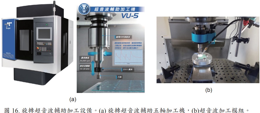
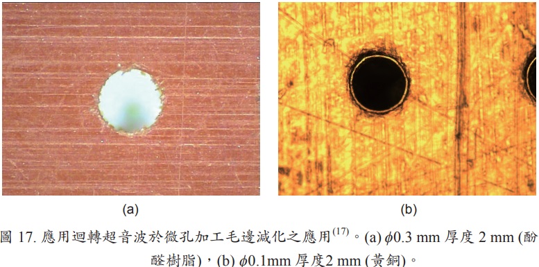
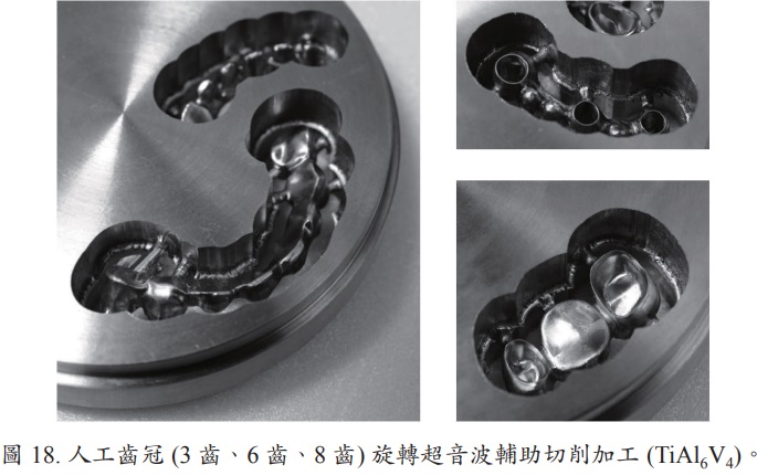
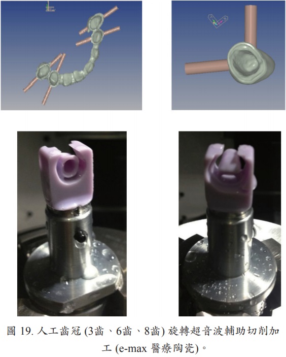
It combines the material removal mechanism of diamond tools with ultrasonic machining (USM), which combines the dual motion of high frequency vibration and high speed rotation of axial aerospace end mills to form a combined abrasive and impact-damaging material processing technique that can easily process high hardness and brittle materials. In rotary ultrasound-assisted milling applications, including drilling, milling, and polishing processes, machining efficiency, tool wear life, and surface finish are key considerations. In the area of rotary ultrasonic assisted milling, the research focuses on the relationship between material removal rate and process parameters, including amplitude, static force, speed, number of abrasive grains, and abrasive diameter (18); in the area of polishing, the research focuses on the surface processing of sapphire brittle materials. Fig. 16 shows the rotary ultrasound-assisted 5-axis machine of this department, Fig. 17 for microporous machining, and Figs. 18 to 19 for artificial crown (titanium alloy, medical ceramic) complex surface machining.
V. Characterization and geometric measurement of complex surfaces for online milling
Based on the need for research on hard-to-cut material process milling models, cloudization of processing data, intelligent operation of collaborative tooling machines, and tool life detection and tool breaking prediction, the axial forces, torques, bending moments in X-Y direction, and temperatures during the milling process are measured and exported to a computer in real time through a toolholder with sensors for tool life evaluation, tool design development, process improvement, and productivity enhancement. The information on milling characteristics collected by evaluating actual milling tests can be used as a reference for selecting milling cutters for milling machining and for planning the path of the cutter (equal milling force). The end mill life detection and tool breaking prediction are shown in Figure 22.
Bending moments and temperatures in the direction of the end mill are measured and exported to a computer in real time for tool life evaluation, end mill design development, process improvement, and increased productivity. The information on milling characteristics collected by evaluating the actual milling test can be used as a reference for selecting milling cutters for milling machining and for planning the path of the cutter (equal milling force). The end mill life detection and tool breaking prediction are shown in Figure 22.
In-process measurement refers to the measurement of a surface when the surface milling is completed, and the tooling machine's milling cutter is replaced with a probe (probe). In the field of manufacturing integration system, the integration of numerical control tool machine milling with online measurement and CAD/CAM system can achieve the goal of process systematization and computerization, enhancing the image and competitiveness of the industry. Important considerations in online measurement include setting the orientation of the workpiece, measurement procedures and path planning, collision assessment, error estimation, and error compensation and correction (19, 20).
To reduce scrap, reduce machine downtime, increase productivity, and provide flexibility for a wide variety of small-scale production, the tool probe can be used to identify components to select the correct NC program, locate reference features to establish a workpiece coordinate system, check part size to confirm machining balance and rough milling procedures, and measure part orientation (relative to machine axis) to perform coordinate rotation. In addition, using the aerospace end mill setter, you can measure the cutter length to establish the cutter diameter correction and check that the cutter length is within the set tolerance and measure the diameter of the aerospace end mill in rotation to establish the cutter diameter correction value.
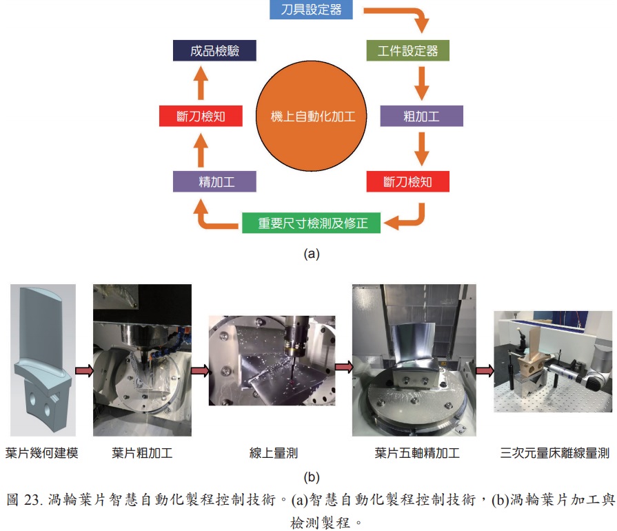
For in-process monitoring, Productivity+TM Active Editor Pro tool probe software is used to plan the measurement paths. The purpose is to confirm the amount of allowance after machining and the accuracy of the surface after finishing, and to assess whether the aerospace end mill paths should be compensated to improve machining accuracy and process efficiency. To avoid programming errors or interference with surfaces, the measurement path must be verified by virtual machine path simulation before actual machine measurements are made. Figure 23 shows the intelligent automated process control technology for turbine blade manufacturing, which integrates geometric modeling, 5-axis machining, and online and offline geometric measurement techniques.
VI. Conclusion
In the future, advanced materials that are lightweight, tougher and more resistant to high temperatures will be widely used. The combination of a 5-axis machine and a compounding machine will maximize the range and type of machining possible on a single machine. It is also because five-axis CNC machining technology is very helpful to the manufacturing of high value precision parts such as aerospace parts in terms of product accuracy and cost efficiency.
Through the integration of CAD/CAM system, virtual reality integration technology, composite process technology and intelligent automated process control technology, the development of process technology for hard-to-cut aerospace parts can not only ensure product accuracy and delivery time, but also collect and analyze the real-time production information of each production equipment and online milling load to provide the most suitable manufacturing conditions and discover the root causes of abnormalities, which will be more efficient and competitive in production.