Micromachining of Stainless Steel Using TiAlN-Coated Tungsten Carbide End Mill
2020-06-22
Abstract
Micro-channels have been used for introducing chemical reactions, mass transfer and/or heat exchanger in some functional micro-devices. Micro-milling process using a micro-end mill to mechanically shear off a work material is normally employed to precisely cut the channel. Although a number of published studies have revealed some effects of micromachining parameters on cut dimensions and process performance, a very little discussion has been made on the cut surface quality and material removal rate in the machining of micro-channel. Hence, this study aims at investigating the effects of machining parameters on these two aspects. AISI 304 stainless steel was selected as a work material to be machined by a TiAlN-coated tungsten carbide end mill. A set of experiments was carried out where the workpiece was cut under the different feed rates and depths of cut. Channel width, depth, surface roughness, burr height and material removal rate were considered as the process responses in this study. A multiobjective optimization was also performed to determine a machining condition optimally balancing both the cut surface quality and material removal rate. The condition associated with the feed rate of 30 mm/min and cut depth of 2 μm was found to be a suitable one to promote the good quality of micro-channel and high machining rate. The findings presented in this study could widen the understanding of process behaviors and offer a guideline for process optimization.
1. Introduction
The needs for miniature devices and micro-components have been emerging in various applications such as medical devices, robotics, automotive parts, aerospace and energy. An example is the manufacturing of microchannels for feeding chemical substances and introducing chemical reactions in a micro-reactor. Since the performance of micro-reactor is dependent on the characteristics of micro-channels, the geometrical dimensions of the channels including shape and surface finish must be specifically fabricated in order to maximize the reactor’s efficiency. Micromachining process using a cutting tool to mechanically shear off a work material is a typical method to manufacture the micro-channels as well as other micro-features in a substrate.
The quality of cut channel is greatly dependent on end mill geometries and machining conditions. In micromachining process, the size effect is an important matter causing different cutting mechanics and end mill-workpiece interactions from the macromachining process. Therefore, the optimum condition set for the micromachining operation is not necessarily the same as the macro-scale one. Hence, there are many studies investigating the effects of micromachining parameters on the cutting mechanics, end mill-workpiece interactions and quality of cut features obtained. Biermann and Steiner investigated the influence of cutting tool geometry, cutting speed and feed per tooth on burr height in the micromilling of austenitic stainless steel, and they found that the use of high cutting speed together with high feed per tooth can promote the burr height especially when up-cut milling strategy is used. Kiswanto et al also found that using high feed rate and shallow depth of cut can introduce a large burr formation in the micromilling of 1100 aluminum. The burr is not only formed along the top edges of cut channel, but also in the bottom surface of the channel.
Such bottom burr is more apparent when the cutting tool is subjected to the large end mill wear. This in turn leads to the plunging of cutting edges into the work material instead of shearing action, thus forming the large burrs along the cut. Although the cutting tool having the positive rake angle and large helix angle can reduce the burr formation, the end mill tends to be easily worn out due to the weakness of cutting edges. Besides the end mill geometries, Biermann et al compared the cutting tool performance by considering different coating materials in the micromilling of AISI 304 stainless steel. Each end mill cutter having a diameter of 1 mm is coated by a single layer of CrN, TiN, AlCrN, AlTiN and TiAlN, and their investigation revealed that the TiAlN, AlCrN and AlTiN coated end mills can demonstrate a higher resistance to wear than the others. A similar suggestion on the coating material is also presented in a study of Dumkum et al, where the TiAlN-coated WC end mill can offer high hardness and good adhesion to the WC substrate. The smallest channel width reported in the above literatures is 0.2 mm, while a much smaller channel is currently of high demand in the manufacturing as it can further enhance the overall performance of micro-devices such as improving the chemical reactions in the micro-reactor.
In addition, there has still been a little discussion on the cut surface quality together with the material removal rate in the machining of micro-channels. It is anticipated that there is a trade-off between the obtained quality and cutting rate, but this relationship has not been explicitly presented elsewhere. In this paper, the micromilling of stainless steel for making a micro-channel is experimentally investigated. The effects of major machining parameters on the dimensions and surface roughness of cut channels are to be examined to bring a further insight into the process. An optimum machining condition balancing between the cut quality and material removal rate is also determined to yield an acceptable cut feature with the maximum possible cutting rate. A step advance in understanding of machining parameters’ influence will be gained from this study, and the findings will provide an essential guideline for the process optimization in the micromachining of stainless steel or other similar metals.
2. Materials and methods
Stainless steel grade 304 was used as a work sample in this study, where a 10-mm long micro-channel with the dimension of 100×100 μm was cut in the metal sheet. A TiAlN-coated tungsten carbide square end mill (WOTEK) was selected as a cutting tool since the high hardness and good adhesion of TiAlN film on the WC substrate can enable a high resistance to wear and prolong the end mill life. The tool diameter (D) was 100 μm and it had two flutes with the helix angle of 30 degrees. A recommended cutting condition taken from the end mill manufacturer is the spindle speed (N) of 40,000 rpm, feed rate (vf) of 40 mm/min and cut depth (d) of 1 μm. The feed per tooth (f) can be calculated by using:

where n is the number of teeth or flutes. Regarding this recommended condition, the calculated feed per tooth is 0.5 μm/tooth. Since a CNC machine used in this study (JDLPC16_A8, Jingdiao, China) can only reach the maximum spindle speed of 35,000 rpm, the feed rate had to be decreased to 35 mm/min to maintain the same feed per tooth of 0.5 μm/tooth. In addition, the recommended depth of cut is only 1 μm, thus requiring 100 milling passes to make a 100-μm deep channel as shown in Fig. 1. To decrease the machining time by half, the depth of cut of 2 μm was also tested in this study. By applying a deeper cut, the feed rate of less than 35 mm/min should be used to avoid the end mill failure. Hence, the feed rates of 20, 30 and 40 mm/min were examined in this study. The experiments were carried out in accordance with the full-factorial experimental design and the replication of each condition was two to satisfy the statistical confidence interval, thus making the total number of tests of 12 runs. The stainless steel sheet was held on the vacuum table of the CNC machine with the pressure of -60 kPa as shown in Fig. 2.
%20Schematics%20of%20milling%20path%20for%20making%20a%20100-%CE%BCm%20deep%20micro-channel%3B%20(b)%20Micrograph%20of%20100-%CE%BCm%20flat%20end%20mill%20used%20in%20this%20study_.jpg)
Fig. 1. (a) Schematics of milling path for making a 100-μm deep micro-channel; (b) Micrograph of 100-μm flat end mill used in this study
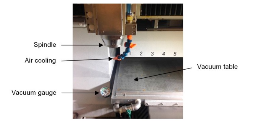
Fig. 2. CNC machine with a vacuum worktable
The channel width, depth and burr height of each cut sample were observed and measured by using a confocal microscope (HRM-300, Huvitz), and the average roughness (Ra) of the channel bottom surface was quantified by using a profilometer (SV-3000, Mitutoyo, Japan). The material removal rate (MRR) of the process was also considered in this study and it can be calculated by using:

where D, vf, d and n are end mill diameter, feed rate, depth of cut and number of flutes, respectively. Regarding Eq. (2), the MRR of machining conditions accounted in this study is listed in Table 1.
Table 1. Material removal rate (mm3 /min) of each machining condition

3. Results and discussion
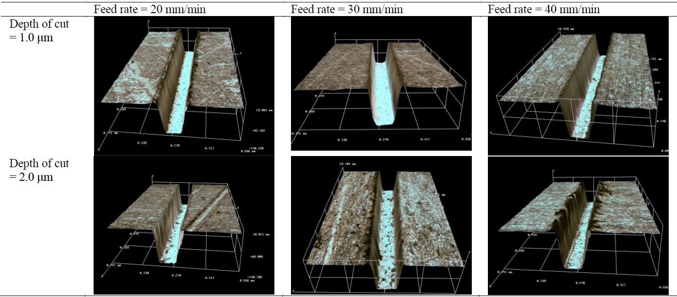
The effects of feed rate and depth of cut on average channel width and depth are shown in Fig. 3(a) and (b), respectively. The micrograph of cut channels is also presented in Table 2. According to the results, the channel width was slightly larger than the end mill diameter with the average error of 6.4 μm. The channel width was insignificantly changed at the feed rates of 20 and 30 mm/min. An explicit interaction was, however, found at the 40-mm/min feed rate, in which a deeper depth of cut introduced a narrower channel and vice versa. The use of high feed rate basically causes a large volume of material to be removed and a large deformation at the cut region. When the feed rate of 40 mm/min is applied together with the small cut depth (1 μm), the cutting load taking place at the end mill edges is plausibly within the performance limit where the chip removal is still well performed without clogging. By contrast, using the combination of high feed rate and large depth of cut may cause chip clogging or even the adhesion of material debris on the cutting edges. Such characteristics lead to the improper shearing action and poor dislodging of cut chips during the process. This consequently changes the rake angle of cutting tool to be a more negative value and then converts the machining mechanics from shearing to plunging. According to this effect, a narrow cut channel is anticipated as a result.
%20Average%20width%20and%20(b)%20depth%20of%20micro-channels%20obtained%20under%20the%20different%20machining%20conditions_.jpg)
Fig. 3. (a) Average width and (b) depth of micro-channels obtained under the different machining conditions
Table 2. Surface morphology of cut channels caused by micromilling process with the different feed rates and cut depths
As presented in Fig. 3(b), the channel depth induced by the different depths of cut was not clearly discernable. All cut channels were found to be deeper than the desired depth of 100 μm by approximately 25% for all feed values tested in this study. While the end mill position and end mill-length compensation were carefully measured and set up before starting each experimental run, the stainless steel sheet used in this study was not perfectly flat and the small deflection of the metal sheet might be responsible for this deviation of cut depth. The use of 30-mm/min feed rate can provide the channel depth close to the desired one regardless of the cut depth applied. This finding also corresponded with the recommended feed from the end mill manufacturer that the feed rate of 35 mm/min or the feed per tooth of 0.5 μm/tooth could offer a good cut result. Since the effects of cut depth on the channel width and depth were not so significant at the feed rate of 30 mm/min, the use of 2-μm depth per pass was therefore applicable to yield a good cut result with the machining time reduced by 50% from the manufacturer-recommended condition.
%20Average%20burr%20height%20and%20(b)%20bottom%20surface%20roughness%20of%20micro-channels%20obtained%20under%20the%20different%20machining%20conditions.jpg)
Fig. 4. (a) Average burr height and (b) bottom surface roughness of micro-channels obtained under the different machining conditions
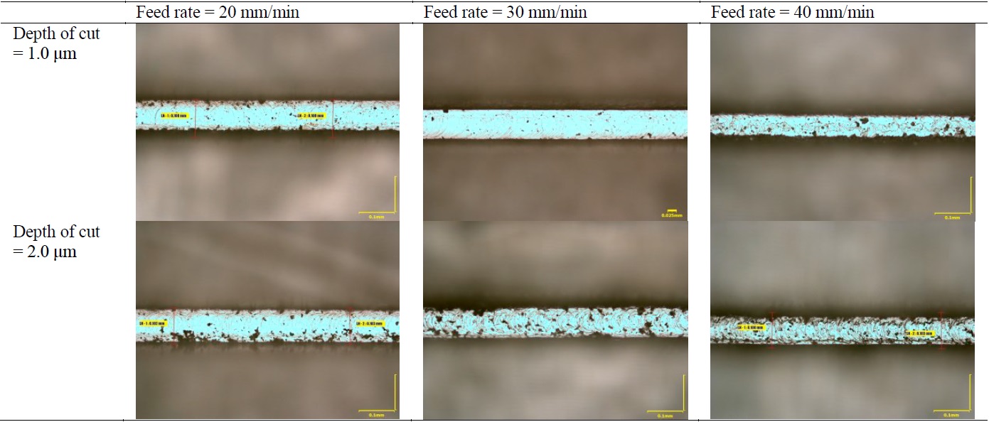
The effects of machining conditions on average burr height and surface roughness are shown in Fig. 4. The average burr height was about 5.6 μm, except the two conditions of lowest and highest cutting loads. The burr height of 55.3 μm was obtained under the combination of slow feed rate and small depth of cut. By using this condition, the plunging effect likely dominates the shearing mechanism due to the very small uncut chip thickness. This can cause a large plastic deformation at the end mill-workpiece contact, where the flow of metal protrudes upward along the channel edges. The end mill-induced rubbing action on the work surface was also found to increase the average surface roughness of the cut channel as presented in Fig. 4(b). The consequence of this plunging effect can also lead to the increased end mill wear and cutting force. A similar finding is reported by Kiswanto et al, showing that the burr formation in the aluminum cutting is introduced by using high feed rate together with small depth of cut. The significant burr was also apparent at the high feed rate and large cut depth condition. The high cutting load and poor chip removal are responsible for the chip clogging in the channel. This result also corresponds to the study of Biermann and Steiner, noting that the burr height significantly increases with the feed rate. Some cut elements are likely to adhere to the bottom surface of the cut channel, and some tend to be extruded as burrs at the channel edges. The adhesion of cut debris was found to deteriorate the surface morphology of cut channel as shown in Table 3. Kiswanto et al consider this effect as the bottom burr and its formation is proportional to the degree of end mill wear. Although the lowest surface roughness of 0.428 μm was achievable at the feed rate of 20 mm/min and cut depth of 2 μm, a number of debris were found to adhere to the bottom surface of the cut channel. A better surface quality providing low roughness and nearly free of bottom burr can be obtained at the 30-mm/min feed rate and 1- μm depth of cut as presented in Table 3.
Table 3. Bottom surface of micro-channels caused by using the different feed rates and cut depths
The selection of a suitable cutting condition is subject to the individual process response. A machining condition that offers the smallest dimensional errors is not necessarily the same as that providing the lowest surface roughness. To cope with the multi-objective optimization for all aspects, the weighted-average method was employed in this study by normalizing all measured data and then defining a decision factor. The normalized response of i condition (y* i) is expressed as:

where yi is the measured response of i condition. The dimensional error of width and depth, burr height and average surface roughness were considered to be the-smaller-the-better case, whereas the material removal rate (Table 1) was the-larger-the-better. All normalized values of a specific condition were averaged with the same weighted value of 1/n, where n is the number of process responses. A decision factor (ηi) for i cutting condition can thus be calculated by using:

The optimum condition equally satisfying all aspects has the highest number of decision factor. As shown in Fig. 5, the maximum ηi is 0.739 belonging to the cutting condition of 30-mm/min feed rate and 2-μm cut depth. With this condition, the channel width and depth of 107 and 117.9 μm can be obtained with the average surface roughness of 0.644 μm and the burr height of only 5.07 μm. The total machining time for making a 10-mm long channel was about 17 minutes. The micrographs of end mill after cutting the channel are presented in Fig. 6, indicating that there is a sign of chipping at the cutting edges. Moreover, the adhesion of cut debris to the end mill surface, called built-up edge, was noticeable on the flank face of cutting tool. This could be due to the poor sliding condition at the end mill-chip interface that prevents the cut chip to be effectively dislodged from the cutters. Although an increase in cutting speed or spindle speed can plausibly reduce the built-up edge and improve the cut surface quality, the high wear rate and burr formation are anticipated to be apparent. This could lead to the poor cut surface quality and shorten the end mill life. Since the CNC machine used in this study was already run at its maximum speed, the effect of cutting speed in this particular micromachining process could be further investigated to widen the understanding of process behaviors and to determine a better cutting condition onward.
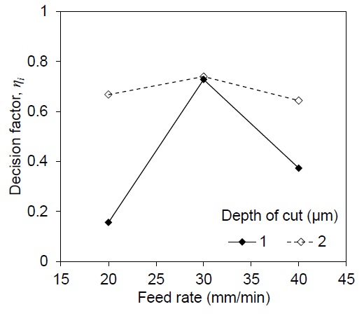
Fig. 5. Relationship between feed rate, depth of cut and decision factor
%20Rake%20face%2C%20(b%2Ce)%20side%20view%20and%20(c%2Cf)%20end%20view%20of%20new%20and%20used%20cutting%20tools%20after%20machining%20a%2010-mm%20long%20channel.jpg)
Fig. 6. (a,d) Rake face, (b,e) side view and (c,f) end view of new and used cutting tools after machining a 10-mm long channel
4. Conclusions
A micro-channel having the size of 100×100 μm was machined in the AISI 304 stainless steel sheet. The influences of feed rate and depth of cut on the channel dimensions, surface roughness, burr height and material removal rate were experimentally investigated and analyzed in this study. An increase in feed rate of greater than 30 mm/min enlarged the channel width and depth particularly at the cut depth of 1 μm. Though the use of cut depth of 2 μm can double the material removal rate offered by the 1-μm depth, the burr height and average surface roughness were found to significantly increase and these in turn deteriorated the quality of cut channel. A multi-response optimization associated with the weighted-average method was applied to determine a suitable machining condition. This can evenly compromise all aspects considered in this study. The average dimensional error of 12.45%, burr height of 5.07 μm, surface roughness of 0.644 μm and material removal rate of 0.00942 mm3 /min were achievable by using the 30-mm/min feed rate together with the 2-μm cut depth. The implications of this study could bring a better understanding of micromachining behaviors and also provide a guideline for the process optimization in terms of cut quality and material removal rate in the micromachining of stainless steel or other similar metals.