FEM Analysis to Optimally Design End Mill cutters for Milling of Ti-6Al-4V
2020-06-19
Abstract
This paper presents an FEM analysis conducted for optimally designing end mill cutters through verifying the cutting tool forces and stresses for milling Titanium alloy Ti-6Al-4V. Initially, the theoretical tool forces are calculated by considering the cutting edge on a cutting tool as the curve of an intersection over a spherical/flat surface based on the model developed by Lee & Altinas. Considering the lowest tool forces the cutting tool parameters are taken and optimal design of end mill is decided for different sizes. Then the 3D CAD models of the end mills are developed and used for Finite Element Method to verify the cutting forces for milling Ti-6Al-4V. The cutting tool forces, stress, strain concentration (s), tool wear, and temperature of the cutting tool with the different geometric shapes are simulated considering Ti-6Al-4V as work piece material. Finally, the simulated and theoretical values are compared and the optimal design of cutting tool for different sizes are validated. The present approach considers to improve the quality of machining surface and tool life with effects of the various parameters concerning the oblique cutting process namely axial, radial and tangential forces. Various simulated test cases are presented to highlight the approach on optimally designing end mill cutters.
1. Introduction
The usage of Ti-6Al-4V is widespread now-a-days in automotive, aerospace and bio-medical industries due to its several inherent properties, such as low thermal conductivity, low elastic modulus, and its capability to withstand varying loads at higher temperatures. Even though Ti-6Al-4V is utilized in different domains, machining Ti-6Al-4V is difficult because of its higher hardness, high specific strength at elevated temperatures. The composition and mechanical properties of Ti-6Al-4V are shown in Table 1 & 2. As most of the mechanical energy used to remove material becomes heat in machining process, high temperature is generated in the cutting region. Due to this fact, the machined chips can easily adhere to the cutting tool and on the machined surface which encounters rapid tool wear. For Ti-6Al-4V, this problem is more severe due to their low thermal conductivity as 80% of the heat generated in the cutting region goes to the cutting tool. To avoid these problems, it is a well-known fact that cutting fluids are used. But still the damages in the finished surface of Ti-6Al-4V can be easily noticed in case of high speed machining process. Many researchers attempted to solve the problem by adopting various optimization methods to control the process parameters and by utilizing different cutting fluids. Some suggested the usage of cutting tool materials with high hardness will reduce heat affected zones, improves the work piece quality, production rate and the tool life. Despite these efforts, the problem is encountered in many scenarios and this research attempts to resolve this issue by adopting a method of optimally designing suitable end mill tool which produces less cutting forces, improve quality of machining surface and tool life. In this paper, various cutting tool forces in the machining process are calculated by considering end mill (ball & flat) for machining Ti-6Al-4V. Later, based on the cutting forces, FEM analysis has been carried out considering Ti-6Al-4V as the work piece material to optimally design end mills. In order to have a better understanding of the problem the forth coming section provide a brief review of research work conducted in a broad domain of milling Ti-6Al-4V.
Table. 1 Composition (wt. %) of Ti-6Al-4V
%20of%20Ti-6Al-4V.jpg)
Table. 2 Mechanical properties of Ti-6Al-4V at room temperature
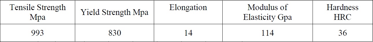
Nomenclature
Ft, Fr, Fa / Tangential, radial and axial force
Sz / Feed tooth, mm
s Feed (mm/ minute)
Rpm / Spindle speed
As / Average value of chip thickness(mm)
Zs / No of teeth in simultaneous engagement with work
Pz / Tangential force (N)
Px / Axial force (N)
Py / Radial force (N)
P / Total force (N)
Ks / Specific cutting force (Kgf/mm2)
Sz / Feed tooth, mm
s Feed (mm/ minute)
Rpm / Spindle speed
As / Average value of chip thickness(mm)
Zs / No of teeth in simultaneous engagement with work
Pz / Tangential force (N)
Px / Axial force (N)
Py / Radial force (N)
P / Total force (N)
Ks / Specific cutting force (Kgf/mm2)
2. Literature of Review
Lee and Altintas applied the geometry and kinematics of the ball end milling process and predicted the cutting forces accurately in tangential, radial, and axial directions. They developed a model and measured the fundamental cutting parameters, the yield shear stress, the average frictional coefficient on the rake face and shear angle from a set of orthogonal cutting tests performed at various cutting speeds and feeds. Ahmad Yasir et.al presented an approach on Minimum Quality Lubrication (MQL) and proved it to be effective in terms of end mill life and surface roughness and at certain cutting speeds. They mentioned that MQL is less effective at higher cutting speeds due and higher pressure is needed to ensure that the mist particle to penetrate into the cutting zone. Puneet Tandon et.al proposed a geometric model of the cutting end mill from the viewpoint of shape realization. A mathematical model of the end mill is developed and the geometry of the cutting tools are expressed in terms of various bi-parametric surface patches. Finally, by solving the geometry of cutting tool equations, they validated the surface models of the end mill. Abbas Fadhel et.al predicted that the feed rate is the most dominant on the cutting force, followed by the axial depth, radial depth of cut and then the cutting speed. Experiments were conducted to verify that the accuracy of the cutting force values using Genetic network (GN) and it was found to be 92%. Their approach proved to be a successful technique that can be used to predict the longitudinal cutting forces produced in end milling.
Dimitrov et.al proposed a method to verify that the cutting speed is the most influential parameter concerning end mill life. They conducted experiments and verified that the major causes of decreased end mill life are due to increased thermal load and surface hardening of the work material. Later cooling modifications have been introduced and the thermal load is reduced by providing by aiding the removal of the heat generation at the cutting zone. The effect of feed rate on surface roughness has been investigated by Nagi Elmagrabi et.al by comparing it other cutting parameters. They noticed that flank wear, adhesion and thermal crack at high cutting speed are the dominant failure mode when machining Ti-6Al-4V with PVD carbide end mill. Experiments were performed to verify the vibration of high speed ball end milling by Lee et.al. It is noted that when high-speed ball end milling is used in a cantilevershaped thin plate, the vibration at the end part of the work piece was severe and was affected considerably by cutter orientation. Among the experiments conducted they found the most stable cutting was achieved with a vertical upward cutting orientation and at the lower part of the work piece.
Pai chi chang and Wang lin presented a model for evaluating the quality of the actual working profile of a taper ball-end milling cutter with a cylindrical shank. In their work, they attached the cutter to the cylindrical surface of the shank and the analysed the process by adopting the minimum circumscribed cylindrical surface (MCCS) of the shank as the datum axis. Using this concept, they defined the minimum circumscribed taper surface (MCTS) and the minimum circumscribed sphere (MCS) to calculate the profile of the spiral groove on the taper part and the ball-end part of the cutter. A mathematical model to measure the edge of the ball nose end mill is proposed by Kuo and Wu. From the calculated data of the edge, a theoretical value is compared with the measured value and a precise assessment was given for processing the ball nose end mill. Engin and Altintas investigated a generalized mathematical model of helical end mills.
In their work, the end mill geometry is modelled by helical flutes wrapped around a parametric envelope. Then coordinates of a cutting edge point along the parametric helical flute are mathematically expressed. Finally, they evaluated the chip thickness at each cutting point by using the true kinematics of milling including the structural vibrations of both cutter and work piece. Johanna Senatore et.al computed the effective radius of milling cutter using the radius of curvature of the envelope curve. In their work they calculated the step-over distance and the effective radius by projecting the curvature of the envelope curve onto a plane perpendicular to the direction of feed motion. A relation was established enabling the angular interval for which the step-over distance of a torus carbide end mill is found to be greater than the step-over distance of a spherical carbide end mill. Engin and Altintas presented a generalized mathematical model for inserted cutters also. The model allowed spacing different inserts on the cutter body mathematically by defining its centre from a cutter body coordinate system. The inserts are oriented by rotating them about the three axes of the cutter body. The insert geometry is defined individually in a local coordinate system by its edge dimensions and shapes. A new experimental method for force coefficients identification considering the inclination angle for ball-end finish milling has been proposed by Qingyuan Cao and Jun Zhao.
The start and exit radial immersion angles were modelled based on different inclination angles. In their work, they analysed that the position of the cutting element on the ball-end mill edge was the only factor to affect the cutting force coefficients in tangential, radial and axial directions. Pioneering studies on the mechanics of chip during machining of titanium alloy or Ti-6Al-4V alloy have been conducted since the early 1950s by Shaw and his co-workers and Boston et al. It is noticed that a large proportion (about 80%) of the heat generated when machining Ti6Al-4V is conducted into the end mill because it cannot be removed with the fast flowing chip due to the low thermal conductivity of titanium alloys, which is about 1/6 that of steels. Also the combination of high stress and high temperature at the end mill tip promote end mill wear and increase production cost. The prominent failure modes in titanium machining were investigated by W Konig and Ezugwu &Wang. They noticed that the failure modes in Ti6Al-4V are notching, crater wear, flank wear, chipping and catastrophic failure which are caused by high temperatures, high pressures, chemical reactivity and the formation of segmented chips. Also Ezugwu &Wang reports that tungsten carbide and PCD are the best end mill materials to machine Ti-6Al-4V. They reported that it is due to a stable TiC reaction layer that is formed between the end mill and the chip.
Cutting speed has been proven to have the most prominent effect of end mill life of all the cutting conditions. End mill life will exponentially decrease as the cutting speed is increased. For this reason, it is common machining practice to machine titanium at a cutting speed of 60 mm/min. It has also been reported that the depth of cut influences the end mill life negatively. End mill geometry also has a significant influence on the end mill life. It has been suggested that a clearance angle of 100 -150 together with a high negative rake angle (-100 to -150) can yield significant improvements. Based on the literature review it has been decided to conduct a research to optimally designing the end mill and to proceed with a FEM analysis for machining Ti-6Al-4V. In order to proceed with the analysis initially the theoretical end mill forces are calculated and CAD models of end mills are created. Then using the CAD model FEM analysis has been conducted in ANSYS workbench. For ease of understanding, the rest of the paper is presented as follows: (i) Section 3 explains the end mill geometry and force analysis conducted for Ti-6Al-4V (ii) Section 4 provides the details of the FEM Analysis of end mill tool for milling Ti-6Al-4V (iii) Section 5 describes the simulation and results and (iv) Section 6 on conclusions and scope for future work.
3. End mill Geometry and Force
Analysis in this research, the geometrical model already developed by Altintas and Lee has been considered for calculating the forces while milling Ti-6Al-4V. Slight modifications have been made to suit the need of the present work and same is reproduced here for better understanding. A detailed geometry of a ball end milling cutter is shown in Fig.1.1-1.3.
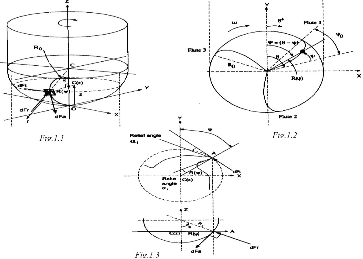
Fig.1.1 -1.3 Geometry of a ball milling cutter1,2&3
Each flute lies on the surface of the hemisphere, and is ground with a constant helix lead. The flutes have a helix angle of io at the ball-shank meeting boundary. Due to the reduction of the radius at the x-y planes towards the tip in the axial (z) direction, the local helix angle i(ψ) along the cutting flute varies for constant helix lead cutters. The expression for the envelope of the ball part is given by : X2 + Y2 + (Ro-Z)2 = R2 ….Eqn (1) Where Ro is the ball radius of the cutter measured from the centre of the sphere. The cutter radius in the x-y plane at axial location Z is R2 (Z) = Z2 + Y2 ….Eqn (2 )And it is zero at the ball tip. The centre of the local coordinate system coincides with the global coordinate system X-Y-Z on the dynamometer shown by ball tip point 'O' in the Figure.1.1-1.3.
3.1 Force Analysis
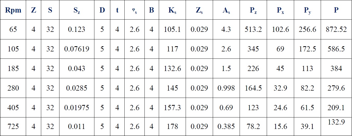
In the milling operation, cutting tool generates tangential, radial and axial forces on the work piece. In the present work, to design the cutting tool, force calculations for different normal features (Figure.2) has been completed for different types of cutting tool geometries using MATLAB. While calculating the forces the cutting conditions (spindle speed,feed,depth of cut,average chip thickness etc) are taken based on standard handbook data. Then using these conditions, the cutting forces namely tangential, radial and axial forces acting on the end mills are calculated. The results obtained from MATLAB is shown in Tables 3 & 4. It clearly indicates that when the spindle speed increases, the cutting force decreases which results in lower value of cutting temperature and giving an improved end mill life.
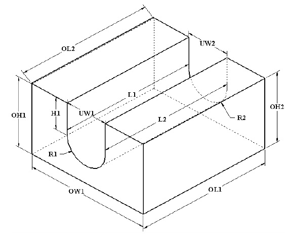
Fig.2 Ordinary through slot with curved base
Table.3 Calculation of cutting force
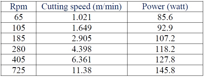
Based on the results the graphs shown from Fig.3.1 to 3.3 have been plotted. They represent the relationship between feed tooth vs. force (Fig.3.1), force vs. speed (Fig. 3.2) and speed vs. power (Fig.3.3). The three graphs indicate that as feed increases gradually force increases and in the same way when speed increases force is decreasing (Fig. 3.2). It means forces will increase if feed and speed increases. In the last graph (Fig.3.3) it is understood that the cutting speed and power increase proportionally.
Table.4 Calculation of cutting speed and power
%20Vs%20Force%20(N).jpg)
Fig.3.1 Plot between Feed tooth (mm) Vs Force (N)
%20Vs%20Speed%20(rpm).jpg)
Fig.3.2 Plot between Force (N) Vs Speed (rpm)
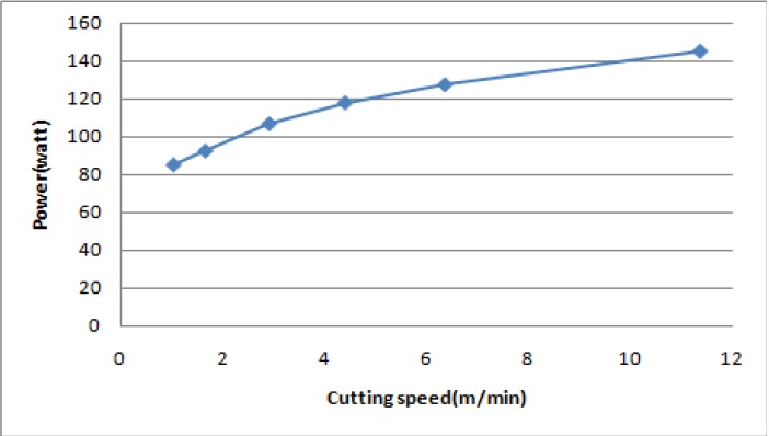
Fig.3.3 Curve of Cutting speed (m/min) Vs Power (watt)
4. FEM Analysis of End Mill Tool for Milling Ti-6Al-4V
4.1 Analysis of Tungsten Carbide End Mill Tool While Milling
Ti-6Al-4V Work piece Based on this analysis, it is decided to proceed with a simulation by optimally designing an end mill using the obtained values. The CAD model is created using Autodesk inventor software and assembled with a rectangular block (which is considered as work piece) and imported to ANSYS work bench. In ANSYS workbench transient structural analysis is considered as this type of analysis is used to determine the dynamic response of a structure under the action of any general time-dependent loads. Then the material properties are added to the imported CAD model. After attaching CAD model of the end mill and work piece, settings related to part geometry, coordinate systems and reference temperature are inputted. It is then meshed as shown in Fig.4 and simulated with higher mesh density on contact surfaces to allow contact stresses to be distributed in a smoother way.
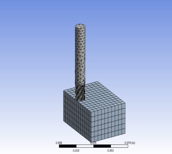
Fig.4. Meshing of end mill tool and work piece
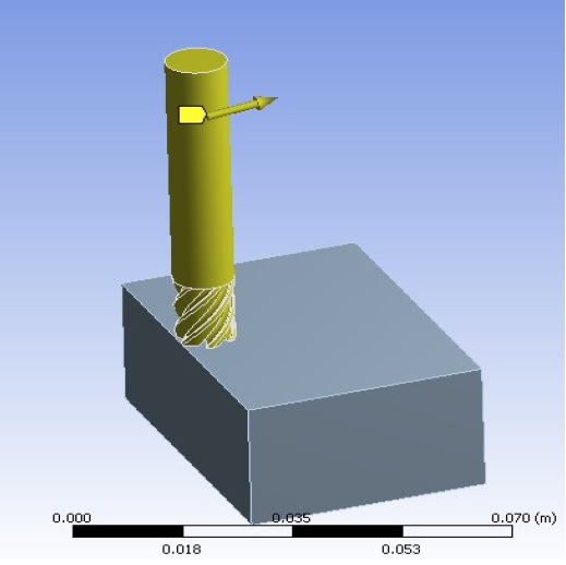
Fig.5. Applying all settings to the end mill
4.2 Analysis Settings
Analysis settings include many options for finding the stress analysis. Step controls are used to control the time step size in a transient analysis. They are used to perform two distinct functions like defining steps and specifying analysis settings for each step. All these details are given from Table 5-7. Figure.5 shows a screen shot of the part after applying all the necessary settings.
Table.5 Details of analysis setting
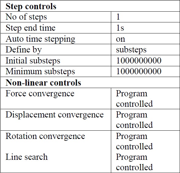
Table.6 Details of rotational velocity
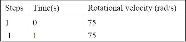
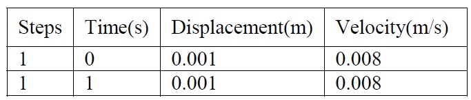
Table.7 Details of velocity
5. Simulation and Results
In the present work, dynamic analysis of the tungsten carbide end mill tool on Ti-6Al-4V work piece are simulated using ANSYS workbench software. The simulation results are given in Table 8. Fig.6 and Fig.7 shows the transient structural analysis performed for the present conditions. Also the simulation analysis has been performed for 3 types of milling operations namely slot milling, hole and step milling and various graphs are plotted. Due to page restrictions only few graphs from Fig.8-10 are presented. Fig.8 represents a gradual increase in stresses of the end mill with respect to time. In machining, time period is major criteria as it will affect the end mill life which in turn affects the work piece quality. Also stresses acting over the end mill during machining affect the end mill life. Particularly in milling operations the work done by the end mill must be completed within the time to optimize the stresses as both time and stresses are interrelated to each other. This has been achieved properly and in Fig.9 relationship between stresses and strain are shown (stress increases with respect to strain). Finally, the Fig.10 represents the relationship between the stress and the time period. It clearly states whenever there is an increase in end mill usage the stresses over the end mill is increased. Based on the analysis and plotted graphs the following points are observed:
1. Stresses observed on the optimally designed end mill are lesser.
2. Forces on the end mill are reduced when compared with the values from the existing literatures.
3. End mill life (usage) is improved based on the new optimal design.
4. The end mill life while milling Ti-6Al-4V is observed based on the calculated forces.
5. The simulated values and the calculated values are closer to each other and can be taken a potential direction for further research.
Table.8 Machining conditions and von mises stress
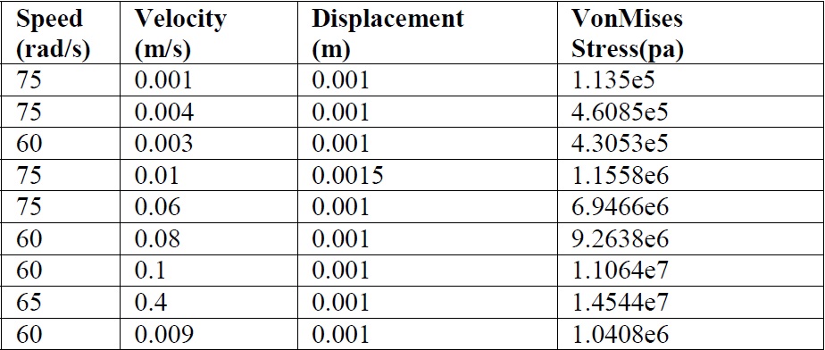
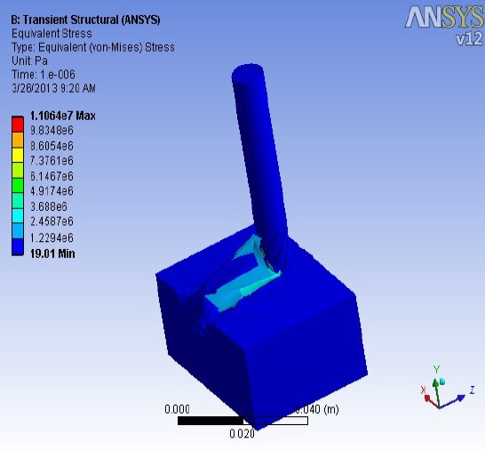
Fig.6 Equivalent stress-1
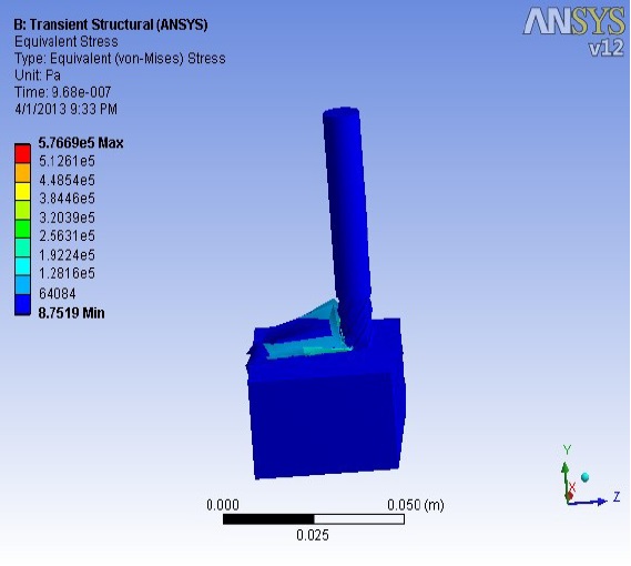
Fig.7 Equivalent stress-2
%20vs_%20minimum%20and%20maximum%20Stress%20(pa).jpg)
Fig.8 Relationship between Time(s) vs. minimum and maximum Stress (pa)
%20vs_%20Strain%20during%20end%20mill%20tool%20analysis.jpg)
Fig.9. Relationship between Stresses (pa) vs. Strain during end mill tool analysis
6. Conclusions and Scope for Future work
In this paper, an approach to calculate the end mill tool forces while milling Ti-6Al-4V has been presented by using end mill geometric equations. Standard cutting conditions of milling machines are considered and cutting velocity, forces, power are calculated for the better performance of end mill. The optimal design of end mill including end mill insert are developed using Autodesk Inventor and were simulated using ANSYS. The obtained results indicate that the predicted forces and simulated forces are closer to each other. Based on these observations it is decided to carry out further work to experimentally verify the dynamic stresses and forces of end mill while milling Ti-6Al-4V considering appropriate machining parameters.