Study on the milling stability of titanium alloy thin-walled parts considering the stiffness characteristics of tool and workpiece
2020-05-15
Abstract
In order to eliminate the chatter in the milling process of titanium alloy thin-walled parts, the milling dynamic model was established taking the stiffness characteristics of tool and workpiece into consideration. The modal analysis and milling experiments were carried out respectively to acquire the system dynamic performance parameters and the milling force coefficient. The cutting stability lobe diagrams were drawn under different stiffness conditions. The results show that the model is valid and the accuracy of lobe diagrams was verified by the milling experiments with different depths of cut.
1. Introduction
The performance of modern aircraft is improved continuously, so in the design process, the monolithic components and thin-walled structures have to be used by designers to improve the equipment performance, such as the integral panels, framework shells and thin-walled members etc.
Despite of the obvious advantages of thin-walled parts, it is still a major problem that the deformation and severe vibration are apparent in the machine process, due to the complicated process and poor rigidity. The concept of chatter was firstly proposed by F.W.Taylor in 1907, since then, the chatter mechanism has been explored by many experts and scholars. The linear model with simplified process system and nonlinear model taking the nonlinear factors of cutting process and machine tool structure have been established. There has been a great leap forward for the chatter theoretical development so far, but the research is still in its infancy level. The guiding effect of chatter theory plays a weak role in the practical production, which remains to be further researched. The theoretical model established under conventional conditions can’t be applied for the thin-walled parts because of poor rigidity, and it is more difficult to guarantee the process stability for thin-walled parts.
Altinas analyzed the dynamic displacement caused by cutting force in the axial, tangential and radial directions for various milling cutters, and established a dynamic model taking the influence of cutting force in each direction on process stability into consideration. Budak and Altintas studied the influence of tool structure parameters,
cutting speed, depth of cut and width of cut on the cutting stability on the basis of dynamic model, and explored the frequency domain simulation and experimental verification of dynamic stability in the axial direction under different machining conditions for thin-walled parts. Gonzalo simulated the cutting process of aluminum alloy thin-walled parts by FE software to optimize the cutting conditions, improve the machining accuracy and surface quality. On the one hand, Gonzalo employed the mechanical model simulate the milling process in the time domain, on the other hand, he employed the FE model to obtain the dynamic characteristic parameters of parts in different processing stages. Bravo presented a method for obtaining the instability or stability lobes taking the dynamic behaviors of the machine tool structure and workpiece, and developed a 3-dimensional lobe diagram to cover all the intermediate stages of the milling process of the thin-walled parts.
In this study, a chatter theoretical model was proposed taking the stiffness characteristics of tool and workpiece into consideration aiming at the thin-walled parts. The stability lobe diagrams were established for the milling process using end
mill under different stiffness conditions, based on the necessary parameters obtained by the modal tests and cutting experiments. And the milling experiments with different depths of cut were carried out to verify the accuracy of lobe diagrams.
2. Machining stability theory
The milling dynamic model is applied to the cutting process of thin-walled parts based on the match of tool rigidity and workpiece rigidity, as shown in Fig. 1. It was established based on the traditional model with two degrees of freedom. It is seen that in Fig. 1, the milling cutter assumed with N teeth is considered with two degrees of freedom (x direction and y direction). The DOF of workpiece is the same with milling cutter.
The milling system modes in the x and y directions are assumed uncoupled, then the dynamic equation obtained for the thin-walled parts is
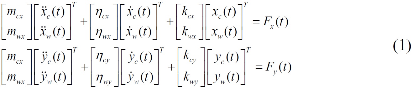
Where, mc and mw are the model mass of the tool and workpiece respectively, ηc and ηw are the damping coefficients of the tool and workpiece respectively, kc and kw are the rigidity of the tool and workpiece respectively. Fx(t) and Fy(t) are the resultant cutting forces in x and y direction respectively when the milling time is t.
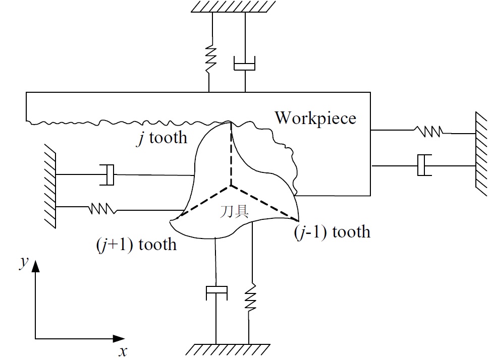
Fig.1. The milling dynamic model based on the match of tool rigidity and workpiece rigidity
2.1. Dynamic chip thickness
The dynamic chip thickness when the j tooth is cutting can be calculated through the displacement difference between the current and former tooth, as shown in Eq. (2).

Where Øj is the instantaneous contact angle of j tooth, which is measured clockwise from normal direction to y-axis. The contact angle changes with time as Øj = (j-1) Øp +ωt, when the spindle is rotating with the angular velocity ω. Where Øp is the
tooth spacing angle Øp = 2π / N.
Where Øj is the instantaneous contact angle of j tooth, which is measured clockwise from normal direction to y-axis. The contact angle changes with time as Øj = (j-1) Øp +ωt, when the spindle is rotating with the angular velocity ω. Where Øp is the
tooth spacing angle Øp = 2π / N.
2.2. Dynamic cutting force
The tangential cutting force Ftj and the radial cutting force Frj are proportional to the depth of cut ap and the thickness of cut h.

Where the cutting force coefficients Kr and Kt are constants. All the cutting force units are decomposed in the x, y directions and added. The sum of cutting forces are expressed in matrix form, as shown in Eq. (4).
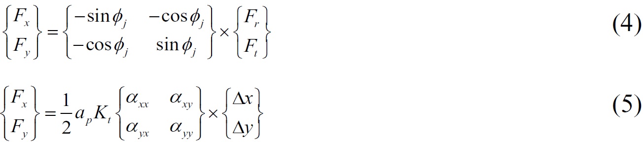
Where αxx, αxy, αyx, αyy are dynamic milling force coefficients changing with time,
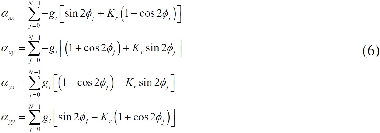
The dynamic milling force coefficients changes with time and the angular velocity, so Eq. (5) can be expressed as a matrix form in the time domain, as shown in Eq. (6).

Where the cutting force coefficients Kr and Kt are constants. All the cutting force units are decomposed in the x, y directions and added. The sum of cutting forces are expressed in matrix form, as shown in Eq. (4).
Where αxx, αxy, αyx, αyy are dynamic milling force coefficients changing with time,
The dynamic milling force coefficients changes with time and the angular velocity, so Eq. (5) can be expressed as a matrix form in the time domain, as shown in Eq. (6).
2.3. The limit axial depth for stable cut
The dynamic displacement generated in the cutting cycle T is shown in Eq. (8).

Where G(iωc) is the transfer function matrix of milling system including the tool and workpiece, namely the frequency response function. The Eq. (9) can be obtained by putting Eq. (8) into Eq. (7).

The system stability can be obtained by the characteristic equation and expressed by the determinant.
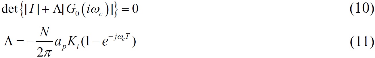
The limit depth of cut aplim and corresponding spindle speed N at chatter frequency ωc can be obtained, after the chatter frequency, the cutting force coefficient, the cut-in angle, the departure angle and the frequency response function are given.
The aplim must be a real number in the practical cutting process, so the imaginary part of Eq. (11) is zero, then
The expression for limit axial depth under the critical condition of stable cutting can be obtained by putting Eq. (16) into the real part of the Eq. (12).
.jpg)
Where G(iωc) is the transfer function matrix of milling system including the tool and workpiece, namely the frequency response function. The Eq. (9) can be obtained by putting Eq. (8) into Eq. (7).
The system stability can be obtained by the characteristic equation and expressed by the determinant.
The limit depth of cut aplim and corresponding spindle speed N at chatter frequency ωc can be obtained, after the chatter frequency, the cutting force coefficient, the cut-in angle, the departure angle and the frequency response function are given.
The aplim must be a real number in the practical cutting process, so the imaginary part of Eq. (11) is zero, then
The expression for limit axial depth under the critical condition of stable cutting can be obtained by putting Eq. (16) into the real part of the Eq. (12).
3. The experiments and discussions
3.1. Design of modal experiments
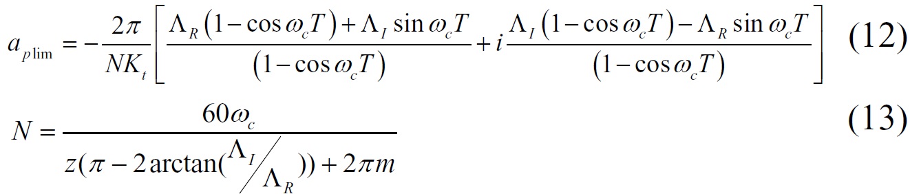
The modal parameters under different stiffness conditions were measured by the modal test apparatus. The single-point excitation and single-point output were adopted, with the forcehammer excitation as motivation mode. The measurement of dynamic characteristics of the tool is shown in Fig. 2.
Fig. 2 The measurement of dynamic characteristics of the tool
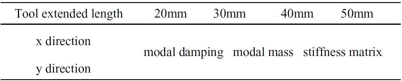
The modal experiments under different tool stiffness conditions are shown in Table 1. The solid carbide end mill was used in the model experiments. The tool length is 112mm, the maximum clamping length is 50mm and the height between the percussion point and the bottom edge is 52mm. The dynamic characteristics of tool were measured in x and y directions by using the milling system dynamic model with two degrees of freedom.
Table 1. The modal experiments under different tool stiffness conditions.
The modal experiment of workpiece is shown in Fig. 3.
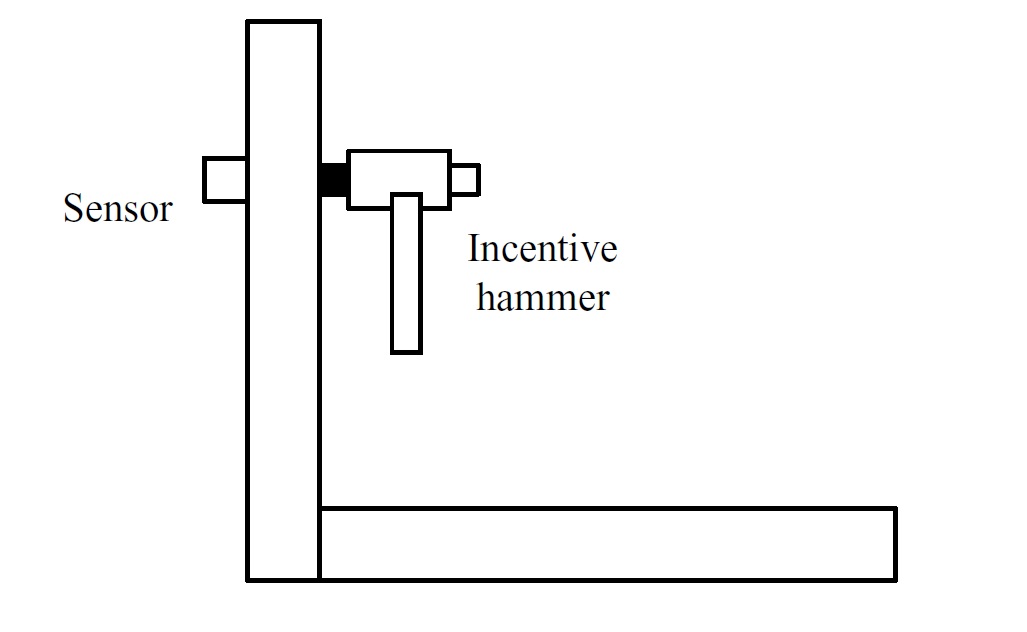
Fig. 3 The modal experiment of workpiece
Two different parts were designed to research the influence of different stiffness on the modal parameters of workpiece. Wherein, the wall panel is located at the side end of bottom for workpiece 1, called as the L-type, as shown in Fig.4. The wall panel is located in the middle of bottom for workpiece 2, called as the T-type, as shown in Fig.5. The total length of each workpiece is 120mm, the initial wall thickness is 20mm. The modal experiment parameters of workpiece are shown in Table3.
Table 2. The modal experiment parameters of workpiece.
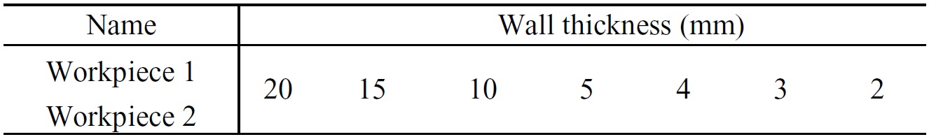
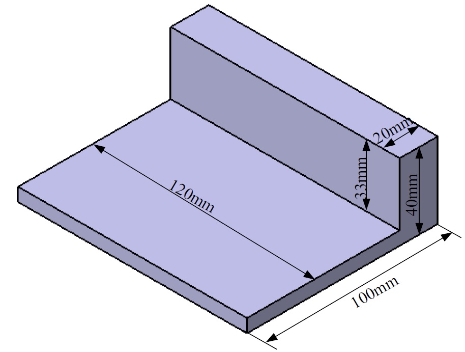
Fig. 4 The model of workpiece 1
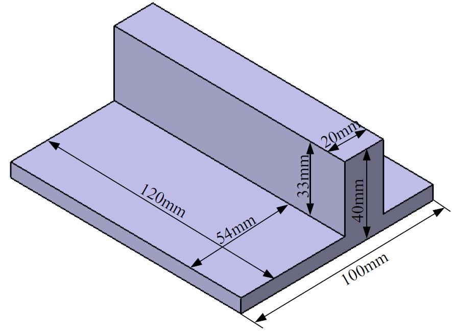
Fig. 5 The model of workpiece 2
The scene photographs of modal experiments are shown inFig.6 and Fig. 7.
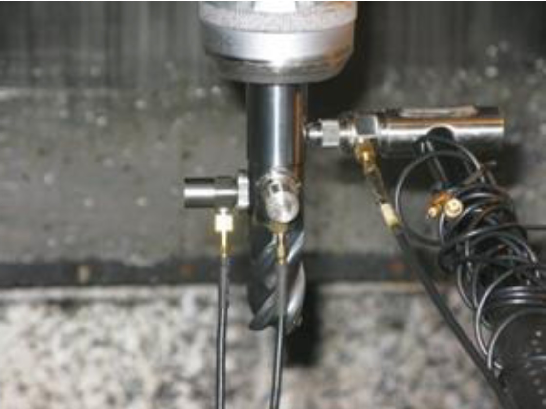
Fig. 6 Modal experiment of tool
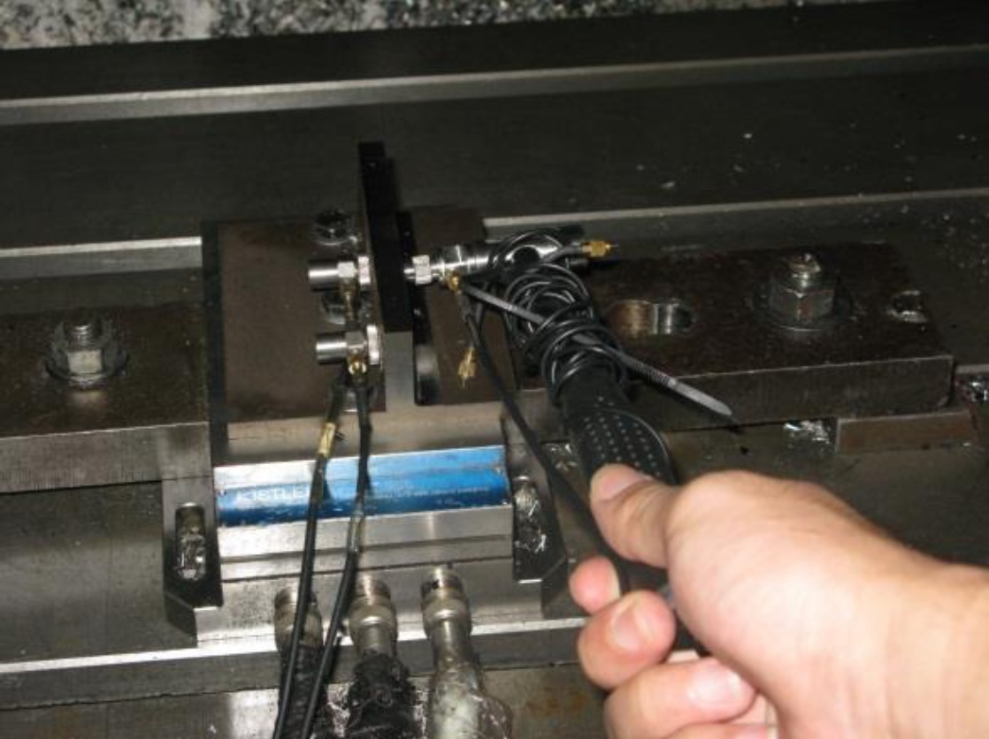
Fig. 7 Modal experiment of workpiece
3.2. Experimental results and discussion
The cutting force coefficients was obtained by experiments with different feed speed, Ktc=965.79N/mm2, Kte=63.662N/mm,
Krc=-2860.7N/mm2, Kre=55.133N/ mm.
The stability of coupled system consisting of the tool and workpiece systems is determined by the sum of transfer functions of the two subsystems when taking the rigidity of tool and workpiece into consideration. And the absolute value of relative displacement is also the sum of two subsystems. So, the frequency response function (FRF) of toolworkpiece is defined as

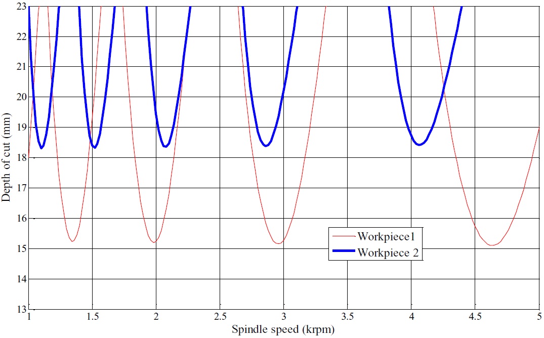
Where c G and w G are the FRF of tool and workpiece respectively. The cutting stability lobe diagrams taking the rigidity of tool and workpiece into account were drawn based on the FRF. The cutting stability lobe diagrams for the workpiece 1 and worpiece 2 are shown in Fig. 8. The wall thickness is 3mm and tool extended length is 72mm. It can be seen that, the axial limit depth of workpiece 2 is larger than workpiece 1, and the number of lobes for workpiece 2 is more than workpiece 1 at the same segment of spindle speed.
Krc=-2860.7N/mm2, Kre=55.133N/ mm.
The stability of coupled system consisting of the tool and workpiece systems is determined by the sum of transfer functions of the two subsystems when taking the rigidity of tool and workpiece into consideration. And the absolute value of relative displacement is also the sum of two subsystems. So, the frequency response function (FRF) of toolworkpiece is defined as
Where c G and w G are the FRF of tool and workpiece respectively. The cutting stability lobe diagrams taking the rigidity of tool and workpiece into account were drawn based on the FRF. The cutting stability lobe diagrams for the workpiece 1 and worpiece 2 are shown in Fig. 8. The wall thickness is 3mm and tool extended length is 72mm. It can be seen that, the axial limit depth of workpiece 2 is larger than workpiece 1, and the number of lobes for workpiece 2 is more than workpiece 1 at the same segment of spindle speed.
Fig. 8 The cutting stability lobe diagrams taking the rigidity of tool and workpiece into account
The milling experiments were carried out to verify the accuracy of the cutting stability lobe diagrams. The depth of cut is 15mm and 18mm respectively for both workpieces. The wall thickness is 3mm, the tool extended length is 72mm, and the other cutting parameters are vc =120m/min, fz=0.05mm/z, ae=0.5mm. The surface photo of workpiece 1 is shown in Fig. 9(a). It can be seen that there are slight vibration marks on the surface when the depth of cut is 15mm, which should be the traces of tool back-off. But when the depth of cut is 18mm, the vibration marks become apparent with the sound harsh, so the chatter occurs.
The cutting force spectrograms of workpiece 1 for ap=15mm and 18mm are shown in Fig. 10. It can be seen that in Fig. 10(a), the vibrations occur on the integer multiple of the passage rate of cutter tooth. However, the vibrations occur on other frequencies in addition to the integer multiple in Fig. 10(b). It shows that the chatter has occurred on these frequencies.
%20the%20surface%20photos%20of%20workpiece%201.jpg)
(a) the surface photos of workpiece 1
%20the%20surface%20photos%20of%20workpiece%202.jpg)
(b) the surface photos of workpiece 2
Fig. 9 The surface photos of workpieces
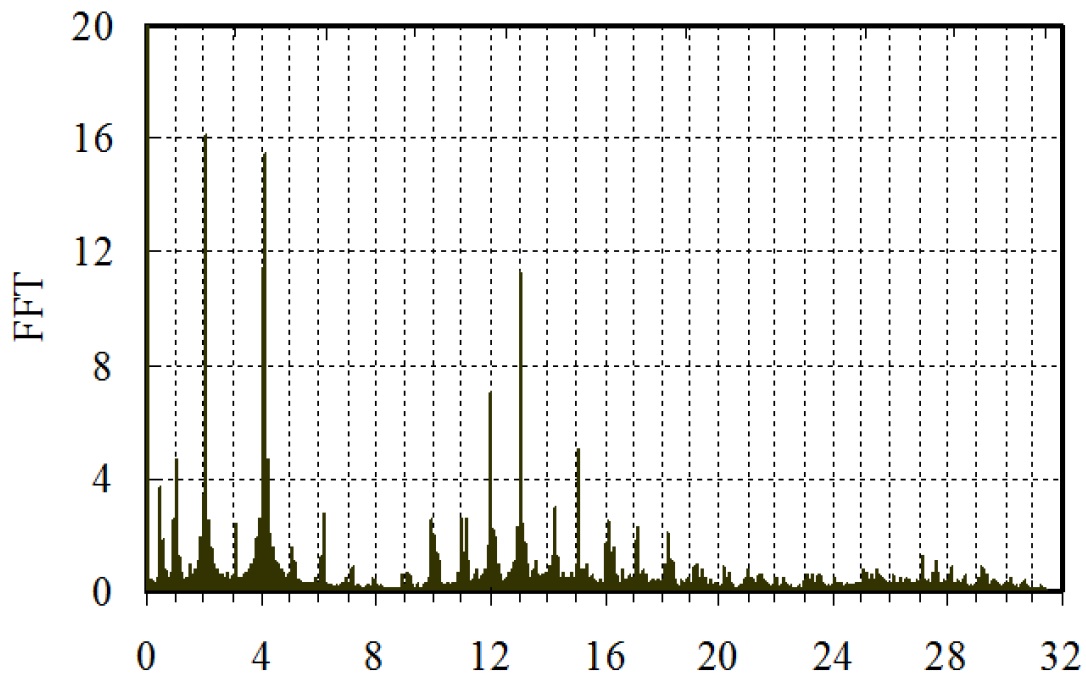
The integer multiple of the passage rate of cutter tooth
(a) ap=15mm
.jpg)
The integer multiple of the passage rate of cutter tooth
(b) ap=18mm
Fig. 10 The cutting force spectrograms of workpiece 1
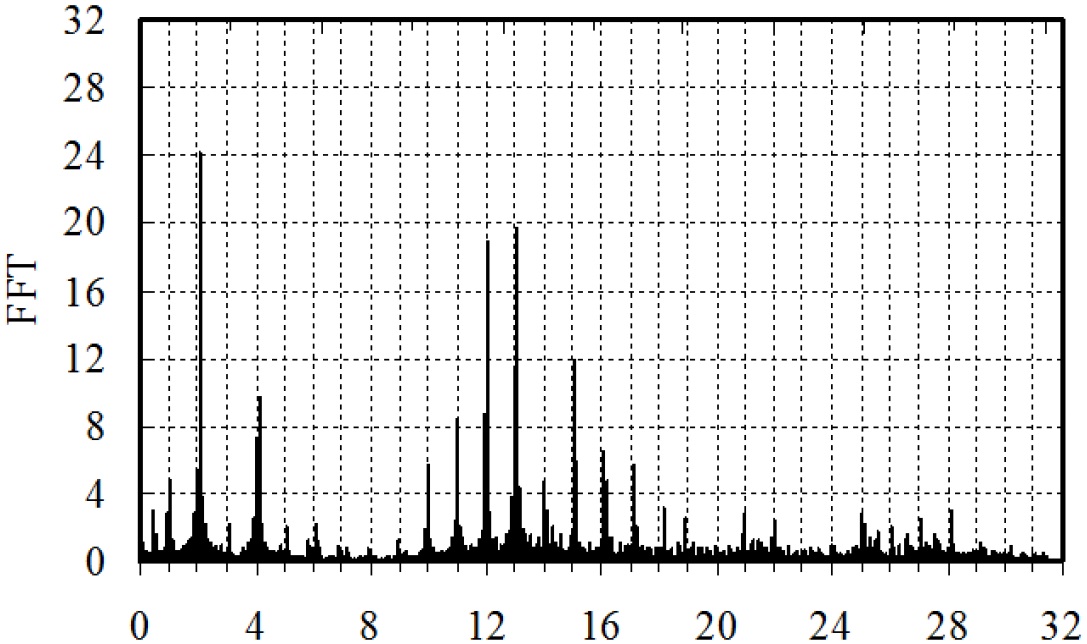
The integer multiple of the passage rate of cutter tooth
(a) ap=15mm
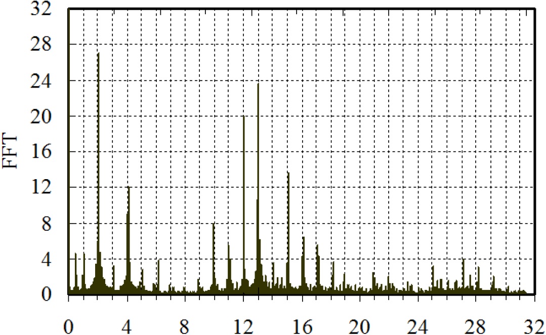
The integer multiple of the passage rate of cutter tooth
(b) ap=18mm
Fig. 11 The cutting force spectrograms of workpiece 2
The surface photo of workpiece 2 is shown in Fig. 9(b). It can be seen that, there are no obvious chatter marks. The vibration marks are the traces of tool back-off. The cutting force spectrograms of workpiece 2 for ap 15mm and 18mm are shown in Fig. 11. It can be seen that all the vibrations occur on the integer multiple of the passage rate of cutter tooth. It shows that the chatter hasn’t occurred, which is consistent with the surface phenomena of workpiece 2.
4. Conclusions
(1) The milling dynamic model was established for the titanium alloy thin-walled parts taking the stiffness characteristics of tool and workpiece into consideration. And the cutting force model for the milling system was also established.
(2) The cutting stability lobe diagrams taking the rigidity of tool and workpiece into account were drawn. And the results show that, the axial limit depths of cut are different under different stiffness conditions. The axial limit depth of workpiece 2 is larger than workpiece 1, and the number of lobes for workpiece 2 is more than workpiece 1 at the same segment of spindle speed.
(3) Cutting test results show that the model is valid and the model can accurately predict the chatter stability in machining Titanium alloy thin-walled components.
Acknowledgements
This work was financially supported by the National Science and Technology Major Project. (No.2013ZX04001 - 021).