Tool Wear in Micro-Endmilling: Material Microstructure Effects, Modelling and Experimental Validation
2020-06-11
Abstract
This paper reports an investigation of material microstructure effects on end mill wear in micro-scale machining of multi-phase materials. A new generic approach is proposed to estimate the end mill wear that utilizes empirical data about the effects of micro milling process on cutting edge radius. Experiments were conducted to study independently the influence of two main phases in steel, pearlite and ferrite, on end mill wear under different cutting conditions. Based on this empirical data two regression models were created to estimate the increase of cutting edge radius when machining single and multi-phase steels. To validate the models, they were applied to predict the end mill wear when machining two different multi-phase steel samples. The results showed a good agreement between the estimated and the actual end mill wear.
1. Introduction
Micro-endmilling is a widely utilized process for producing complex three-dimensional features at micro scale especially when tight tolerances and relatively high accuracy has to be achieved. At the same time due to the growing industrial demand for miniaturized components, a broad range of engineering materials are machined by micro-endmilling. Unlike macro-scale machining, the edge radius of the end mill is in the same order of magnitude as the chip-loads while both are comparable with the grain sizes of the machined materials. Hence, in micro-endmilling operations the effects of material microstructure on surface roughness, cutting forces and end mill wear have to be considered. These scale effects become even more pronounced in the case of multi-phase materials as they are a “blend” of a finite number of phases each with its own distinct properties, and thus with different machining responses under the same cutting conditions. These effects have to be investigated in order to optimize the process and identify processing windows, cutting conditions, which can reduce the resulting surface roughness while extending the end mill life.
The main criteria that can be used for assessing the machinability of any material are the resulting surface roughness, cutting forces and end mill wear. Furthermore, end mill wear leads to changes of the cutter geometry, especially cutting edge radius and cutting end mill corner radius. This can be attributed to the small chip-loads usually applied in micro-milling that result in thermal growth and wear, and as consequence of this in a significant increase of the friction between the end mill and the workpiece. The surface roughness is directly affected by such changes in the end mill geometry but ultimately the end mill wear affects the quality and dimensional accuracy of the machined parts. Therefore, a better understanding of the machining mechanisms and the progression of the end mill wear in micro-endmilling is very important for advancing further this technology.
This paper reports a new approach for modelling end mill wear when machining multi-phase materials at micro-scale together with its evaluation for effectiveness under different machining conditions. In particular, experiments were independently carried out on two different steel samples, pearlite and ferrite steels, to analyses the material effects on end mill wear behavior. Then, empirical models were created to estimate the end mill wear when machining multi-phase samples.
The paper starts with a review of the state-of-art in micro machining, especially the factors affecting the end mill wear. Then, the experimental setup and the experiment design are described for conducting the machining trials. Next, the results are presented and discussed, with a focus on material effects on end mill wear. This is followed by the description of the two regression models created together with their experimental validation. Finally, conclusions are made about the effectiveness of the proposed approach for predicting the end mill wear when machining multi-phase steel workpieces.
2. Literature review
2.1 Material microstructure effects
The cutting regime in micro-scale machining cannot be fully explained using kinematic parameters only. There are other factors that influence and can even determine the underlying cutting mechanism such as those related to the workpiece material, especially its heterogeneity, strain-hardening, elastic recovery and size effects.
Many researchers have investigated the effects of material microstructure in the micro-machining processes. Furukawa and Moronuki reported on different cutting mechanisms for polycrystalline, single crystal and amorphous materials, and also for brittle and ductile materials. It was suggested that by increasing the undeformed chip thickness to ten times the average grain size for a given material, it would be possible to avoid the negative crystallographic effects of the material microstructure.
Weule et al. studied the effect of the material microstructure of steel workpieces, SAE 1045, in the precision fly cutting process. It was argued that, for a good projection of the cutting end mill into the workpiece, the processed material should have only one phase, or its microstructure should be homogenized to reduce the grain diameter of the material when compared with cutting edge radius. Therefore, a pre-heat treatment of the workpiece before its micromachining was proposed in order to homogenize it. Also, relatively large feed rates were suggested for improving surface integrity.
Vogler et al. conducted series of full-slot endmilling tests with two fluted carbide end-mills on single-phase ferrite and pearlite, and also on multi-phase iron. Low frequency cutting forces were observed when machining both pure ferrite and pure pearlite. At the same time high frequency forces occurred when processing the multi-phase iron, which was attributed to the heterogeneity of the workpiece microstructure, and as consequence of this changes in cutting conditions that led to an increase in vibration and the occurrence of highly fragmented chips.
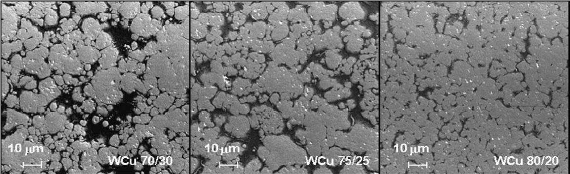
Uhlmann et al. reported an experimental study into micro-milling of sintered tungsten-copper (WCu) composite materials with different ratios of W and Cu and with microstructures as shown in Fig. 1. A strong relationship between surface quality and homogeneity of the material microstructure was observed.
Many researchers have investigated the effects of material microstructure in the micro-machining processes. Furukawa and Moronuki reported on different cutting mechanisms for polycrystalline, single crystal and amorphous materials, and also for brittle and ductile materials. It was suggested that by increasing the undeformed chip thickness to ten times the average grain size for a given material, it would be possible to avoid the negative crystallographic effects of the material microstructure.
Weule et al. studied the effect of the material microstructure of steel workpieces, SAE 1045, in the precision fly cutting process. It was argued that, for a good projection of the cutting end mill into the workpiece, the processed material should have only one phase, or its microstructure should be homogenized to reduce the grain diameter of the material when compared with cutting edge radius. Therefore, a pre-heat treatment of the workpiece before its micromachining was proposed in order to homogenize it. Also, relatively large feed rates were suggested for improving surface integrity.
Vogler et al. conducted series of full-slot endmilling tests with two fluted carbide end-mills on single-phase ferrite and pearlite, and also on multi-phase iron. Low frequency cutting forces were observed when machining both pure ferrite and pure pearlite. At the same time high frequency forces occurred when processing the multi-phase iron, which was attributed to the heterogeneity of the workpiece microstructure, and as consequence of this changes in cutting conditions that led to an increase in vibration and the occurrence of highly fragmented chips.
Uhlmann et al. reported an experimental study into micro-milling of sintered tungsten-copper (WCu) composite materials with different ratios of W and Cu and with microstructures as shown in Fig. 1. A strong relationship between surface quality and homogeneity of the material microstructure was observed.
Fig. 1: Microstructure of WCu
Popov et al. investigated the machining response of mechanically and metallurgically modified Al 5083 alloy when milling thin features in micro components. It was showed that through refinement of the material microstructure it was possible to significantly improve the surface integrity of the machined micro features. For example, by reducing the average grain size from 100–200 μm to 0.6 μm, the surface roughness of the machined features improved three times while the material also became more isotropic. The authors concluded that the roughness of micro features produced by micro-milling was highly dependent on the material grain sizes.
Simoneau et al. observed surface defects as dimples on the machined surface of plain carbon steel. They attributed this phenomenon to the dual phase structure of the workpiece material and the effect of strain mismatch at the grain boundary due to the energy absorbed by the softer grains before they were effectively cut.
Wang et al. investigated the interdependence between physical characteristics of multi-phase materials and machining conditions. According to an equation proposed by the authors the minimum chip thickness is dependent on phases’ friction coefficients. Thus, chips can be formed for grains with high friction coefficients while for grains with lower friction coefficients, only little burrs are created or the material is just compressed.
Aramcharoen and Mativenga carried out a statistical analysis of critical parameters governing the micro milling process of a hardened end mill. In particular, the effects of spindle speed, depth of cut, ratio of undeformed chip thickness to cutting edge radius, and lubrication/environment conditions on matters such as surface finish, burr formation and end mill wear were experimentally examined. The results revealed that surface finish and end mill wear were significantly influenced by the machining environment but also it was stated that for hard and homogeneous materials with low elastic recovery rates, the best surface finish was achieved when the undeformed chip thickness was less than the cutting edge radius.
Mian et al. investigated experimentally the machinability of a multi-phase material, ferrite/pearlite AISI 1045 steel, when machined at micro-scale. The authors aimed to improve the viability of the micro-milling process by studying cutting conditions and strategies required for machining materials with coarse grained microstructures. The authors found that the end mill edge radius and the size of the material grains had a significant influence on the resulting surface roughness. They also concluded that both parameters should be optimized to improve the surface quality. In particular, the cutting end mill wearied rapidly at chip-loads less than the cutting edge radius which in turn led to higher surface roughness, as shown in Fig. 2. Moreover, to reduce burrs formed during the machining of such dual-phase materials, the authors suggested using chip-loads bigger than the average grain size.
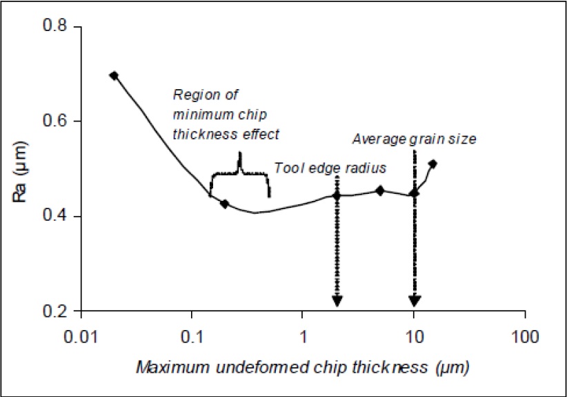
Fig. 2: Effect of cutting edge radius on surface roughness
In a subsequent research, Mian et al. conducted an experimental comparative investigation of two different steels. One was mostly ferritic steel, AISI 1005, while the other was well-balanced ferritic/pearlitic steel, AISI 1045. The authors studied the effect of the material microstructure on the surface finish, microstructure change, burr formation and end mill wear for a range of chip-loads. It was reported that machining of AISI 1005 was more difficult when compared with AISI 1045. In particular, larger burrs were observed when machining AISI 1005 as shown in Fig 3a and 3b. Also, more smearing on the machined surface was noticed over the entire range of feed rates and this was associated with the increased end mill wear. The investigation proved that both chip-load and workpiece material had a noticeable influence on the generated roughness. However, surface finish was more sensitive to end mill edge radius and chip-load than the material grain size. This is reflected in the similar roughness values obtained at chip-loads in the vicinity of the end mill edge radius for both materials despite the different material grain sizes.
%20down-milling%20and%20(b)%20up-milling.jpg)
Fig 3: Burr size in (a) down-milling and (b) up-milling
Goo et al. carried out micro-milling tests to compare the machining responses of plain polystyrene and Carbon Nano-tube (CNT) composite polystyrene in terms of cutting forces, acoustic emissions, and burr formations under a wide range of chip-loads. The shearing regime was found to be more dominant when machining CNT composite polystyrene and this was attributed to the decrease in the minimum chip thickness when the plain material was reinforced with CNTs.
Kota and Ozdoganla examined the effect of the crystallographic anisotropy of coarse grained aluminum on cutting forces at different machining conditions. Significant changes in cutting forces were observed when machining workpieces with different grain sizes and also it was found that the average surface roughness was dependent on the particular crystal orientation. Specifically, the differences in cutting forces and surface roughness could be up to 300% and almost 700%, respectively (Fig. 4). In addition, the authors stated that the specific cutting energy could be reduced by increasing the uncut chip thickness and/or decreasing the cutting speed.
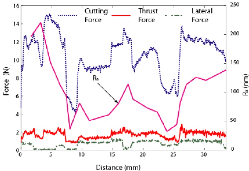
Fig. 4: Variations in surface roughness and forces
The conducted review reveals that material microstructure is an important factor in micro-milling that has to be considered when the end mill wear at micro scale machining is investigated and models are created to predict it.
2.2. Cutting Edge Radius Effect
Deceptively, micro-machining and conventional machining can be considered kinematically similar, i.e. their material removal principles. However, as previously stated, there are a number of key differences between micro-scale and macro-scale machining which arise from changes in the underlying physical phenomena. These changes are mainly attributed to size effects that are dominant factors in micro-scale machining. In particular, due to the reduction in chip thickness which becomes dimensionally of the same order as the cutting edge radius of the cutting end mill, transitional regimes associated with intermittent cutting and ploughing becomes more dominant. Furthermore, when the chip thickness is below a critical value, referred to as minimum chip thickness, chips may not be formed during each tooth pass; instead, the workpiece material elastically deformed. This results in higher cutting forces, larger end mill wear, micro-burr formation, and subsequently the surface quality is affected.
The minimum chip thickness can be defined as the minimum undeformed thickness of a chip removed from the workpiece surface using a end mill with a given cutting edge radius under ideal conditions. The chip thickness is sufficiently large in macro-milling and therefore it is not necessary to consider the effects of edge radius and hence the uncut chip thickness while in micro-milling becomes comparable to the end mill edge radius. Thus, any small change in the chip-load can have a significant influence on the material removal mechanism by altering machining conditions from proper cutting to ploughing or even rubbing. Thus, to eliminate such effects, the minimum chip thickness has to be determined prior to any machining and thus to select appropriate machining conditions.
The effect of the minimum chip thickness, below which neither chip formation nor material removal occurs, was investigated by other researchers employing analytical and experimental methods.
The significance of the minimum chip thickness effect was experimentally investigated by Ikawa et al. By employing a well-defined diamond cutter in face turning of electroplated copper it was possible to form very fine chips with an undeformed thickness in the order of nano-meters and achieve a minimum chip thickness in the order of 1/10 of the cutting edge radius.
Kim proposed a round edge cutting model to simulate the cutting forces in orthogonal machining that took into account the effect of the cutting edge radius and the elastic recovery along the clearance face of the cutter. In particular, the normal and friction stresses on the clearance face of the end mill due to the elastic recovery of the workpiece were considered. In addition, the friction and normal stresses on the round edge, and the effect of the negative rake angle on the shearing geometry were examined. The results obtained with the model were compared with the experimental results reported by Lucca et al. both to validate it and also to assess the feasibility of using it to predict the cutting forces more precisely than what was possible with the conventional sharp edge cutting model.
Yuan et al. performed an experimental study of minimum chip thickness effects on the resulting surface in diamond turning of aluminum alloys. The results showed that the use of larger cutting edge radii led to rougher surfaces, which was explained with the minimum chip thickness effect. Moreover, the minimum chip thickness was determined to be in the range of 20-40% of the cutting edge radius.
Another group, Weule et al., examined the effect of minimum chip thickness on the resulting roughness. The generated surface by micro-cutting of SAE1045 was inspected using a laser-based topography measuring device and the saw-tooth-like profile obtained was attributed to the effect of the minimum chip thickness. Also, the minimum chip thickness was determined experimentally to be 0.293 of the cutting edge radius of the end mill.
Kim et al. conducted experimental trials in order to study the effect of minimum chip thickness on the chip formation process in micro-milling of brass. The experiments were carried out using a range of feed rates, from 0.188 μm to 6 μm, with 635 μm diameter cutter. The authors stated that at very small chip-loads, chips might not be formed during every end mill pass. Moreover, the formed chips had a larger volume than expected when compared to the material volume removed with one end mill pass and this was explained with comparable sizes of the cutting edge radius and the applied chip-load. A conclusion was made that no chip formation would occur unless the chip-loads had reached a certain value, especially a minimum chip thickness.
Kim et al. developed a comprehensive model of chip formation in micro-milling process in order to assess the effects of the ploughing and material elastic recovery alongside the cutter flank face during the micro-machining process. It was found that the ploughing contributed significantly to the cutting forces in micro-milling, especially at low feeds per tooth due to the effect of the minimum chip thickness.
Vogler et al. determined the minimum chip thickness of ferrite and pearlite phases in steel workpieces at micro-scale machining by employing a finite element (FE) model. Different edge radii, from 2 to 7 μm, and a range of chip thicknesses, from 0.1 to 3 μm, were used to estimate the ratio of minimum chip thickness to end mill edge radius, which was found to range between 0.14-0.25 and 0.29–0.43 for pearlite and ferrite, respectively.
Lai et al. studied the size effect in micro-milling of Oxygen Free High Conductivity (OFHC) copper. A FE model that takes into account the material characteristics and cutting edge radius was used to simulate orthogonal machining at micro-scale. The minimum chip thickness was found to be 0.25 of the 2 μm cutting edge radius when machining copper. Also, the increase of the specific cutting energy at very low feed rates was explained with the dominating ploughing regime due to the minimum chip thickness effect and the accumulated chip thickness.
Biermann and Kahnis also studied the influence of the cutting edge radius in micro-milling. The cutting edge radius of the end mill was enlarged by abrasive water-jet blasting and thus to achieve a range of cutting edge radii. It was determined that the use of larger cutting edge radii led to lower surface quality and higher cutting forces but also lower end mill was achieved. Additionally, it was shown that with low undeformed chip thicknesses, the specific cutting forces and surface roughness increased and the burr formation was significantly higher due to the ploughing effects.
It is evident from the conducted review that the micro-milling process is highly dependent on the cutting edge radius status, especially its increase can alter the machining condition from cutting to ploughing/rubbing and thus to lead to higher cutting forces and uneven surface generation. So, the progression of the end mill wear in terms of cutting edge radius is indicative of the underlying cutting conditions at micro scale and should be investigate to understand better the effects of different process parameters in micro-machining.
2.3. End mill Wear In Micro-machining
The end mill wear was investigated mostly at macro-scale and only a few studies for micro-scale machining were reported. This is due to the limitation of the available inspection methods and difficulties in conducting empirical investigations.
Tansel et al. studied experimentally the relationship between end mill wear (usage) and the cutting force in micro-milling during the machining of soft and very hard materials, especially aluminum and steel. Back propagation-type artificial neural networks (ANN) were used to create models for estimating the end mill wear instead of detecting the pre-failure stage investigated by the authors in prior research. The authors concluded that, in case of aluminum, cutting force variations increased proportionally with the end mill usage which was attributed to changes in the shape of the cutting end mill; cutting edges were gradually losing their sharpness and effectiveness. The ANN models were able to identify dependences between the end mill wear and cutting force during the machining of soft materials. However, the relationship between the end mill wear and cutting forces when machining a steel (NAK 55) workpiece was very different from the aluminum response. Therefore, the proposed ANN can be used to identify the pre-failure stage only when machining NAK 55 workpieces.
Bao and Tansel modelled the cutting forces in micro-milling by considering the effects of the cutting edge trajectory on the chip thickness when the end mill rotates and moves forward simultaneously. The proposed model predicted the cutting forces more precisely than the macro-scale model proposed by Tlusty and Macneil, especially when the ratio of feed per tooth to end mill radius was larger than 0.1. However, this was just the first attempt and more comprehensive models were developed afterwards to account for the effects of end mill run-outs, and end mill wear that could be utilized to monitor the condition of the cutting end mill on-line.
Malekian et al. examined experimentally the effect of cutting conditions on end mill wear in micro-endmilling, and proposed a monitoring method that relied on sensory data obtained employing accelerometers, and force and acoustic emission sensors. A neuro-fuzzy method was used to combine such data and study the condition of the cutting end mill, especially to determine whether it was sufficiently sharp for normal machining to continue. To verify the proposed monitoring method, cutting trials were performed using 500 μm diameter flat micro-end mills, while an optical microscope was used to inspect the cutting end mill corner radius. According to the authors, the proposed method can be used to monitor the conditions of the micro-end mills online and thus to provide warnings when the end mill reaches the pre-failure state. However, it is important to stress that in this research only the condition of the cutting end mill corner radius was monitored to estimate the end mill wear, and not the cutting edge radius, which has a greater influence on the resulting surface finish and cutting forces.
Lia et al. proposed a regression model to estimate the end mill wear. The average reduction of the nominal end mill radius as a function of the material removal volume and cutting velocity was used to judge the end mill condition. Due to difficulties in measuring small cutters the widths of the machined channels were measured to indirectly judge end mill wear. In this research, the regression model of the end mill wear was employed to calibrate the trajectory-based surface generation model and thus to predict its effects on surface roughness variation. It was stated that the effect of the end mill wear on the resulting surface finish was significant; for some conditions, the roughness increased several times with the increase of end mill wear, and therefore should be considered when modelling the effects of micro-endmilling on the machined surface. However, the effect of end mill geometry changing due to wear, such as the increase of the cutting edge radius, was not considered in this research.
Jun et al. studied experimentally the effects of the cutting and ploughing machining conditions on end mill wear by applying different feed rates. Also, the authors introduced a new parameter to quantify end mill wear during micro-endmilling. In particular, the increase of the cutting edge radius, denoted as Δre, was defined as a new wear parameter, which was calculated employing the following equation:
where re1 and re2 are the cutting edge radii for the first and second flutes, respectively, while the subscript, w or n, denotes worn and new end mills.
Dependence between the applied feed rates and the wear mechanisms was identified and it was possible by varying the feed rates to avoid an increase of the “round” wear and minimum chip thickness effect. The authors stressed that by selecting an appropriate processing window favorable machining conditions could be maintained. Especially normal cutting above the minimum chip thickness with a predominantly flat flank end mill wear was maintained without increasing the cutting edge radius. However, it is worth noting that the end mill wear parameters were assessed only before and after the machining trials.
In spite of the limited number of publications in this field, it can be concluded that the end mill wear in micro-endmilling is an important factor affecting the process performance and at the same time it is a challenging research issue that needs addressing. Especially, the machining performance can be improved by understanding better the effects of cutting conditions on end mill wear mechanism. In addition, to carry out such an investigation it is necessary to find new ways, e.g. experimental setups, for characterising and monitoring end mill wear.
3. Experimental set-up and experiment design
This section describes the experimental setup used to investigate the end mill wear during micro-endmilling. In particular, it outlines the basic procedure followed in the experimental trials, and also explains the rationale behind the used materials, cutting end mills and cutting parameters in the trials.
Changes in the cutting edge radius and the cutter flute profile were chosen to quantify the end mill wear because of their higher importance in modelling the micro-endmilling processes and also in predicting the resulting surface roughness. To investigate the effects of these two end mill parameters on the machine, a new experimental setup was designed and implemented as shown in Fig. 5. It allows the cutting conditions to be maintained unchanged during the trials as there is no need to take off the cutters for offline inspections.
The adopted procedure to investigate experimentally the end mill wear in micro-endmilling includes the following steps. First, after removing a certain volume of material, the cutter was cleaned using Delta GT-7810A ultrasonic cleaner for 30 sec. Then, a Blum NANO laser system, P87.0634, was used to measure nominal diameters of the cutters at different heights and thus to judge the cutter flute profile after each trial. Next, a Dino-lite digital microscope with 500X optical magnification was employed to image the bottom of the cutter as shown in Fig 5. To inspect the cutting edge radius of the three cutter flutes, the measurement functions of the Dino-Capture 2.0 software was used as shown in Fig. 6. In addition, a Keyence VHX-2000 digital microscope was used to verify the measurements taken by the Dino-lite microscope and thus to judge its capabilities to evaluate end mill wear progression at micro-scale accurately.
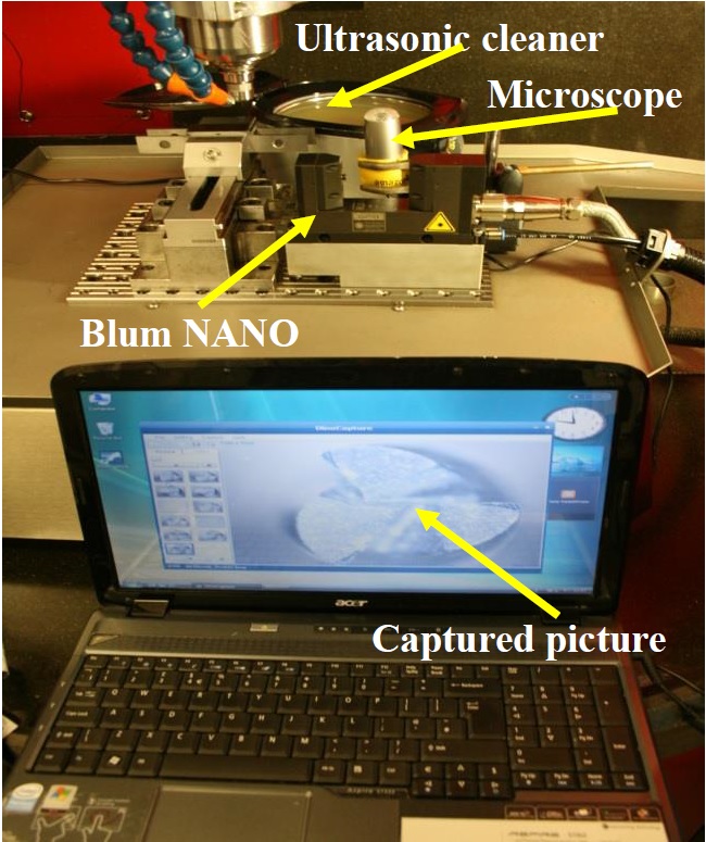
Fig. 5: Experimental setup
To examine the effect of the material microstructure on the end mill wear evolution, two different materials, SAE 01 high carbon steel (0.85-1.05%C) and SAE 101 low carbon steel (0.08-0.13%C), were used for the first part of this research because of their pure pearlite and pure ferrite microstructures, respectively. The effects of each phase on the end mill wear behavior were studied experimentally under different cutting conditions. In particular, the machinability in terms of end mill wear was investigated by carrying out slotting tests on a micro-machining centre, Kern HSPC 2216. Fine grained tungsten carbide 800 μm diameter end-mill cutters coated with TiAlN were utilized in these machining trials. Prior to the cutting tests, each cutter was imaged using an optical microscope and thus to measure the radii of the cutting edges as shown in Figure 7. For the cutters used in the trials they were in the range from 2 to 5 μm. The undeformed chip thickness was controlled by varying the feed rate per tooth and thus to achieve values in the vicinity of the average cutting edge radius for which the best surface roughness was expected, in particular 4 and 8 μm/tooth feed rate were applied. The other cutting parameters used in the trials were two levels of cutting speeds, 20,000 and 5,000 rpm equivalent to 50 and 12.5 m/min respectively, and one depth of axial cut, 30 μm.
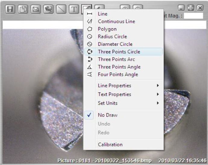
Fig. 6: Measurement functions of the Dino-Capture 2.0 software
%20a%20new%20tool%2C%20(b)%20a%20worn%20tool%20and%20(c)%20and%20(d)%20severely%20worn%20tools%3B%20where%2C%20r%20denotes%20radius%2C%20C%20is%20the%20circumference%20and%20A%20is%20area.jpg)
Fig. 7: The end mill wear evolution in micro-endmilling(a) a new end mill, (b) a worn end mill and (c) and (d) severely worn end mills; where, r denotes radius, C is the circumference and A is area
4. Results and Discussions
4.1 Measurement uncertainty
The end mill wear measurements were conducted manually, and hence there was some uncertainty in performing them. Therefore, the maximum magnification allowed by the software was used to inspect the cutters and thus to minimise the measurement uncertainty. In addition, the measurements were conducted after relatively big increments of removed material and thus to see clearly the progression of the end mill wear. However, it is still necessary to assess the measurement uncertainty associated with the procedure used to inspect the cutting edge radius, re. All measurements were taken with the same magnification and therefore it was assumed that the sources of uncertainty in inspecting the radii were the same for the all measurements. Thus, the equation used for calculating the standard uncertainty, u, is:
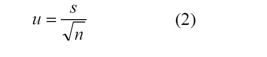
where s is the estimated standard deviation and n is the number of measurements in the set.
To carry out this assessment, five measurements were conducted for each of three different cutting edge radii: two extremes, the lowest and the highest values with one in the middle. Fig. 8 shows the results of the measurements. For the cutting radii with mean values of 2.00 μm, 10.65 μm and 20.41 μm, the estimated standard deviation, s, was calculated to be 0.265 μm, 0.158 μm and 0.112 μm respectively, while the standard measurement uncertainty was 0.12 μm, 0.07 μm and 0.05 μm, respectively. As expected the measurement uncertainty was dependent on the radii nominal dimensions. It was determined that the maximum measurement uncertainty was 0.12 μm for the 2 μm cutting edge radius which was considered acceptable for this study. So, for each cutting flute, all measurements were performed five times and averaged before using adapted Eq. 1 to calculate the increase of edge radius, Δre, for the three flutes of the cutters.
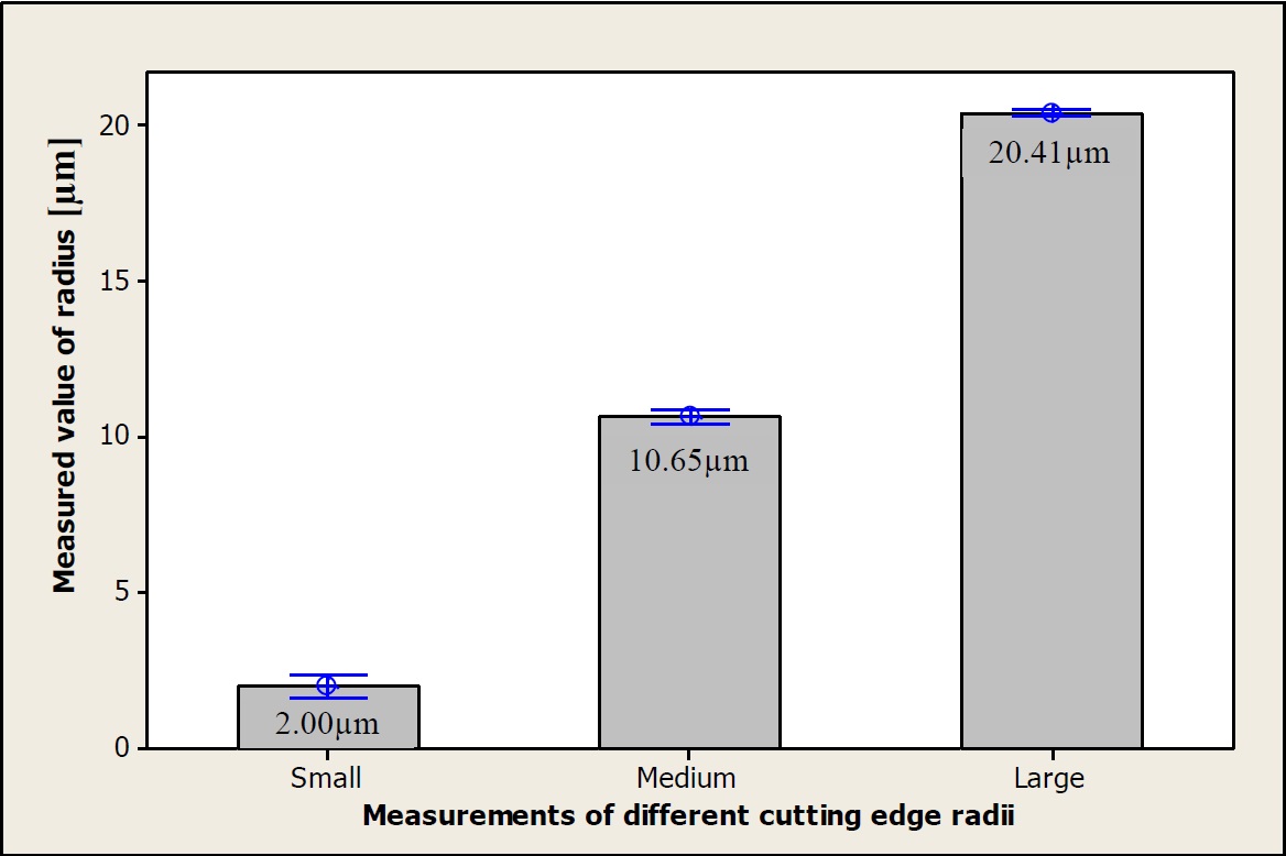
Fig. 8: The results of five measurements carried out at three different cutting edge radii
4.2 End mill wear
The images captured with the microscope were used to assess the wear of the cutting edge radius after removing certain volumes of material. The evolution of edge radius with the increase of the normalised material removal volume, MRn (the removed volume divided by the depth of cut) for the pearlite and the ferrite samples are presented in Fig. 9 and Fig. 10, respectively.
For pearlite, the end mills exhibited the highest wear when the lowest settings for cutting speed, Vc, and feed rate, Fz, were applied, while the lowest wear was measured at the highest setting as shown in Fig. 9. It is worth stressing that the relationship between the end mill wear and the applied feed rates and speeds was contrary to that in macro-scale machining, but was in agreement with results reported by Filiz et al. This end mill wear increase at low feed rates can be attributed to the ploughing regime that dominates the process. In particular, the machining response of pearlite under such settings is influenced by its large elastic recovery, which leads to a higher force being exerted on the cutter and hence a higher wear due to the higher friction between the cutting end mill and the workpiece. The minimum chip thickness effect becomes significant at low cutting speeds because the engagement time of the end mill/workpiece is longer. Moreover, it is not difficult to see that the end mill wear, in particular Δre, is highly dependent on the used cutting speed.
In contrast for ferrite, see Fig. 10, there was only a small variation of Δre when different settings were applied for the cutting speed and the feed rate. However, the linear increase of the end mill wear with the increase of material removal volume was much more pronounced. Ferrite has a lower rate of spring back in ploughing regimes than pearlite but in spite of this a higher end mill wear was observed under the same cutting conditions. This phenomenon can be explained with the differences in mechanical properties of these two phases. The ferrite phase is characterized by a higher toughness, especially when alloyed with even a small quantity of Mn, which contributes to the material ‘build-up’ on the end mill. Therefore, ploughing can be the prevailing machining mechanism rather than cutting when compared with the response of pearlite under the same conditions. This regime dominates and leads to higher cutting forces being exerted on the end mill edge, and hence a more intensive wear of the end mill. At the same time, pearlite is more ‘brittle’ and susceptible to a lower minimum chip thickness, shorter chip formation and favourable cooling conditions for the end mill edge.
%20workpiece.jpg)
For pearlite, the end mills exhibited the highest wear when the lowest settings for cutting speed, Vc, and feed rate, Fz, were applied, while the lowest wear was measured at the highest setting as shown in Fig. 9. It is worth stressing that the relationship between the end mill wear and the applied feed rates and speeds was contrary to that in macro-scale machining, but was in agreement with results reported by Filiz et al. This end mill wear increase at low feed rates can be attributed to the ploughing regime that dominates the process. In particular, the machining response of pearlite under such settings is influenced by its large elastic recovery, which leads to a higher force being exerted on the cutter and hence a higher wear due to the higher friction between the cutting end mill and the workpiece. The minimum chip thickness effect becomes significant at low cutting speeds because the engagement time of the end mill/workpiece is longer. Moreover, it is not difficult to see that the end mill wear, in particular Δre, is highly dependent on the used cutting speed.
In contrast for ferrite, see Fig. 10, there was only a small variation of Δre when different settings were applied for the cutting speed and the feed rate. However, the linear increase of the end mill wear with the increase of material removal volume was much more pronounced. Ferrite has a lower rate of spring back in ploughing regimes than pearlite but in spite of this a higher end mill wear was observed under the same cutting conditions. This phenomenon can be explained with the differences in mechanical properties of these two phases. The ferrite phase is characterized by a higher toughness, especially when alloyed with even a small quantity of Mn, which contributes to the material ‘build-up’ on the end mill. Therefore, ploughing can be the prevailing machining mechanism rather than cutting when compared with the response of pearlite under the same conditions. This regime dominates and leads to higher cutting forces being exerted on the end mill edge, and hence a more intensive wear of the end mill. At the same time, pearlite is more ‘brittle’ and susceptible to a lower minimum chip thickness, shorter chip formation and favourable cooling conditions for the end mill edge.
Fig. 9: The average increase of the cutting edge radius for pearlitic (SAE 01) workpiece
%20workpiece.jpg)
Fig. 10: The average increase of the cutting edge radius for the ferritic (SAE 101) workpiece
The nominal cutting end mill radii at different heights were measured, and examples of typical printouts are provided in Fig. 11 and Fig. 12 for pearlite and ferrite, respectively. The black arrow indicates a reduction of the nominal cutter radius due to the end mill wear. The factors affecting these measurements were end mill run out and vibrations, the thermal elongation during machining and also the presence of some chips due to insufficient cleaning time. Thus, this could explain the differences between their actual and nominal dimensions as new cutters of 400 μm in radius. The repeatability of the Blum NANO laser system that was used to carry out these measurements was considered to be ±1 μm as stated by the manufacturer.
When comparing the results obtained on both, the pearlite and the ferrite workpieces, under the same cutting conditions, there was less end mill wear in regards to the nominal cutter radius when machining pearlite, as shown in Fig. 11, compared with the results for ferrite, Fig. 12. In particular, the reductions of the nominal cutter diameter were 12 μm and 28 μm for the pearlite and the ferrite workpieces, respectively. These results are in agreement with the other wear parameter, cutting edge radius, where the machining of pearlite exhibited less wear compared with ferrite. Again, this phenomenon can be attributed to the mechanical properties of these two phases, as mentioned earlier.
.jpg)
Fig. 11: Cutter radius measurements at different heights for pearlite (SAE 01)
.jpg)
Fig. 12: Cutter radius measurements at different heights for ferrite (SAE 101)
5. Regression based modelling
ANNs is considered a better way to model the end mill wear then regression based models. However, to create such ANNs large data sets are required in order to train and then test the models. This is a major constraint because of the relatively large number of expensive cutting end mills necessary, usually one for each investigated machining setting. So, in this research the experiments were conducted at only two cutting speeds, two feed rates and seven removal rates for each material. An attempt was made to train ANN using 70% to 100% of the available empirical data however the model performed poorly during both the training and testing stages due to the relatively small data set. Therefore, regression modelling was selected in this experimental study to investigate the increase of the cutting edge radius when machining multi-phase materials.
Two regression models were used to analyses the end mill wear, Δre,p and Δre,f for pearlite and ferrite, respectively, as a function of cutting speed, Vc, feed rate per tooth, Fz, and normalized material removal volume, MRn, Minitab 15 software was used to generate the models based on the experimental data obtained by machining the SAE 01 and SAE 1010 samples.
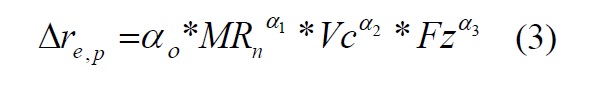
For pearlite, taking into account the observed trend for the end mill wear in Fig. 9, an exponential model, Eq.3, was adopted to achieve the best fit.
Then, a logarithmic transformation was applied to convert Eq. 3 into the linear analytical form shown in Eq. 4:

The least squares’ estimation technique was applied to calculate the coefficients, and thus to create a regression model for estimating the end mill wear when machining pearlite steel at micro-scale.
In the case of ferrite, as the end mill wear trend was very close to linear, see Fig. 10, a linear regression model was adopted. Once again, the least squares’ estimation technique was applied to determine the coefficients and the thus to create the proposed regression model.
The models that were created for pearlite and ferrite phases are given in Eq. 5 and Eq.6, respectively.
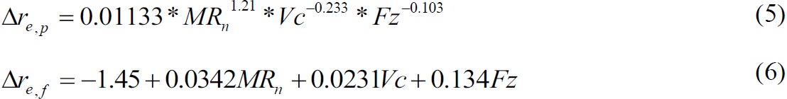
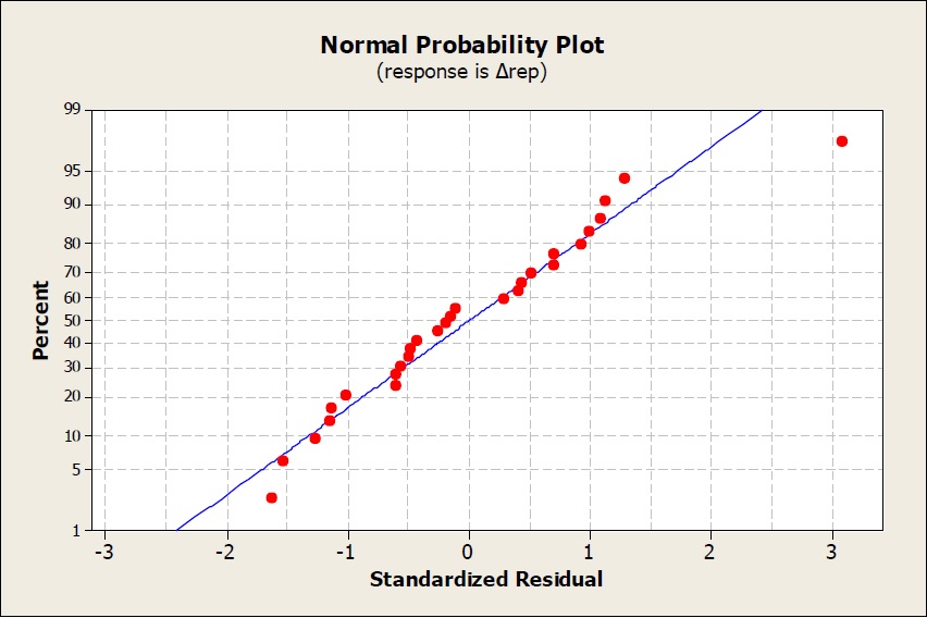
Fig. 13: Normal probability plot of the pearlite wear model
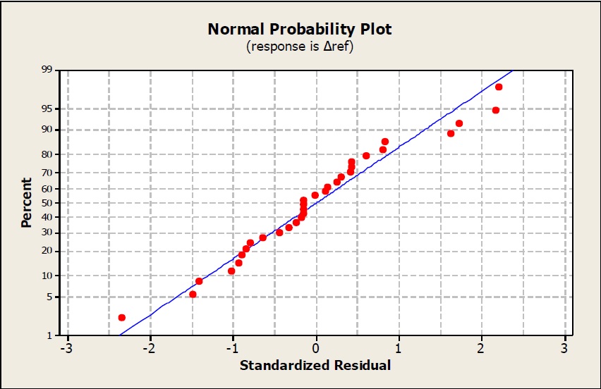
Fig. 14: Normal probability plot of the ferrite wear model
Based on the obtained coefficient of determination for both models, R-Sq, the prediction accuracy for the average wear, Δre,p and Δre,f, was within 91.2% and 97.0% for pearlite and ferrite, respectively. Also, the normal probability plots of the pearlite and ferrite models shown in Fig. 13 and Fig. 14 indicate that most factors that affect the end mill wear are considered in the analysis.
6. Experimental validation
The objective of the second series of experiments was to demonstrate the validity of the proposed method and also to validate the developed regression models. The proposed models were assessed under different conditions and the predicted values of end mill wear were compared with the measured results. The proposed models were used to estimate the end mill wear when machining two different dual-phase steel samples, namely AISI 1040 (0.37-0.44%C) and AISI 8620 (0.18-0.23%C) carbon steels with different ratios of ferrite and pearlite in their microstructure. The machining trials, in particular slotting tests, were conducted with 800 μm diameter cutters and under cutting conditions similar to those used in the first set of experimental trials, in particular, feed rate of 6 μm/tooth, cutting speed of 25 m/min and the depth of cut 30 μm were applied.
Fig. 15a and 15b show the microstructure of AISI 1040 and AISI 8620 steel samples, respectively. The two phases can be seen clearly; the dark one is pearlite while the bright phase is ferrite. The micrographs of both samples were taken to create maps of their metallurgical microstructure and then to calculate the percentage of pearlite and ferrite in them. For the AISI 1040 steel there is a good balance between pearlite and ferrite, 48% and 52%, respectively, while for the AISI 8620 sample the ferrite phase was dominant, 68%. The higher ferrite content, with its higher minimum chip thickness than pearlite, was expected to lead to more ploughing rather than cutting, when compared with the AISI 1040 sample, under the same cutting condition. This ploughing mechanism increases the force exerted on the cutting edge due to the significant increase of the friction between the end mill and the workpiece, which in turn leads to a temperature increase and higher wear.
%20AISI%201040%20and%20(b)%20AISI%208620%20steels.jpg)
Fig. 15: Optical microstructure micrograph of (a) AISI 1040 and (b) AISI 8620 steels
Based on this data, it is possible to account for the effects of these two different phases, and to estimate end mill wear using Eq. 4 and Eq. 5. The same approach can be applied to other multi-phase materials. In particular, the end mill wear model for dual-phase materials can be defined as:

where: Δre is the end mill wear for the dual-phase material; Δre, p and Δre, f is the end mill wear for pearlite and ferrite, respectively; and Rp and Rf are the percentages of these two phases in the dual-phase material.
Fig. 16 shows a comparison of the predicted and the actual end mill wear exhibited when machining the AISI 1040 workpiece with 800 μm diameter end mill, by applying cutting speed of 25 m/min, feed rate of 6 μm per tooth and 30 μm depth of cut. The experimental results have a non-linear trend-line in contrast to the linear one for the predicted wear; the difference between the estimated and the actual end mill wear is on average 14.7%.
Fig. 17 shows a comparison between the prediction and experimental results when machining the AISI 8620 sample under the same cutting conditions as those used for AISI 1040. As can be seen from this figure, the trend is similar to that observed during the machining of the AISI 1040 steel (Fig. 16). Again, there are differences between the predicted and experimental results but again they are relatively low, within 16.4%. Thus, it can be concluded that these results support the use of the proposed approach and the models created to predict the end mill wear when machining dual-phase steels.
Studying the experimental results obtained for both materials (Fig. 16 and Fig. 17), it is not difficult to see the higher end mill wear resulting from the machining of the AISI 8620 workpiece in comparison with the AISI 1040 one under the same cutting conditions. This was expected and was attributed mostly to the higher percentage of ferrite in the AISI 8620 microstructure. Also, the models predicted accurately the wear in both case. Hence, it can be stated that the influence of the material microstructure on the end mills’ wear is significant and by accounting for this, models can be created which accurately predict end mill wear when machining multi-phase materials.
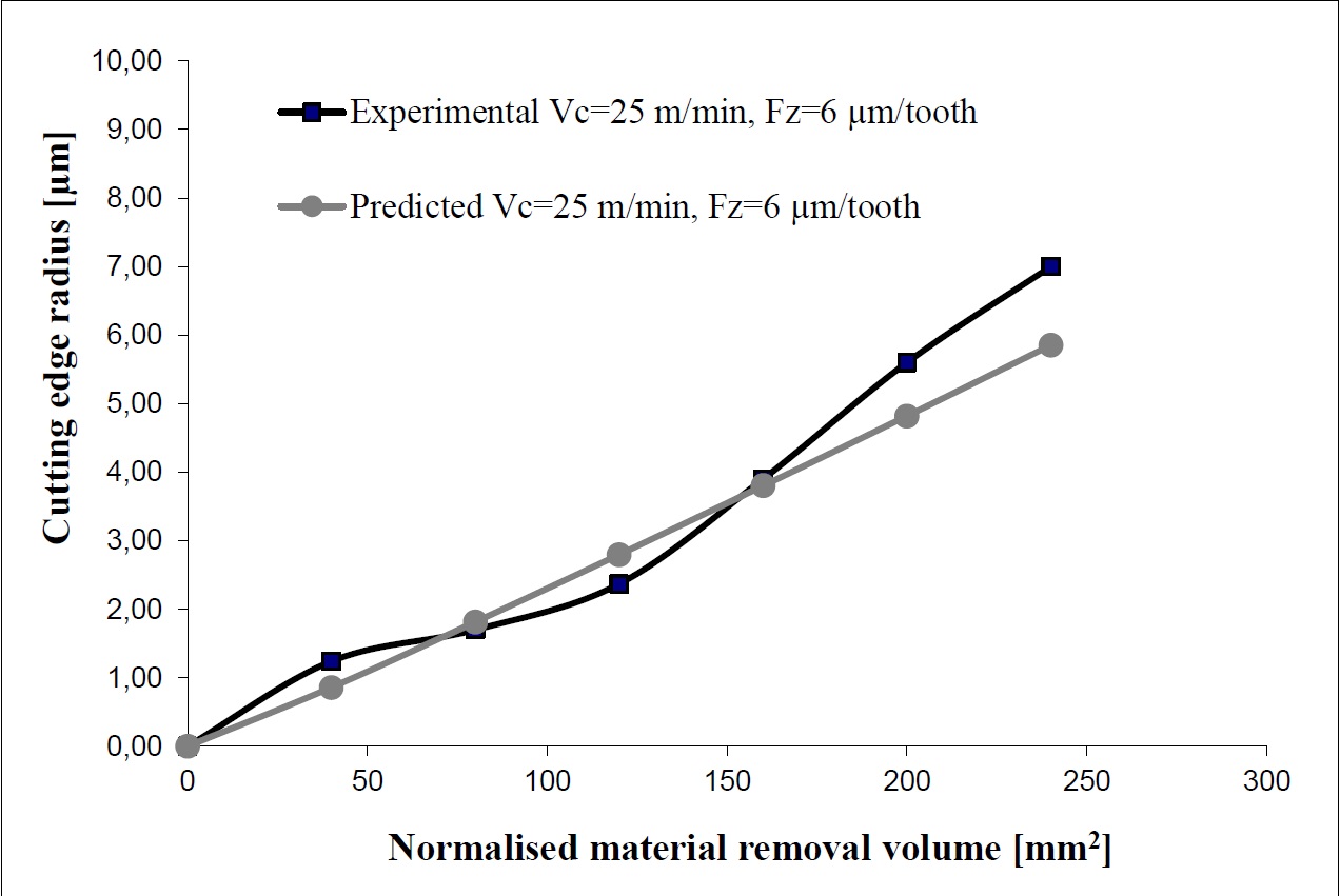
Fig. 16: Comparison between experimental and estimated end mill wear when machining the AISI 1040 workpiece with 800 μm diameter end mill and 30 μm depth of cut
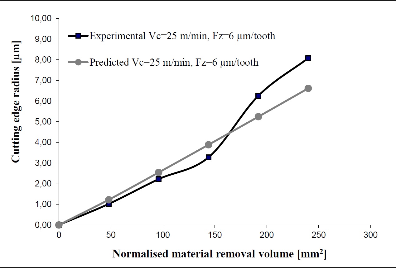
Fig. 17: Comparison between experimental and estimated end mill wear when machining the AISI 8620 workpiece with 800 diameter μm end mill and 30 μm depth of cut
Taking into account the results from all trials, it is evident that the proposed approach can be used to model end mill wear behavior when machining dual-phase materials. It can be argued that the differences between the predictions and experimental results can be reduced by increasing the number of experiments conducted on the pearlite and ferrite samples to generate the data sets used to create the models. Additionally, the engagement of a end mill with more than one phase simultaneously could be another reason for the observed discrepancies.
The same approach can be adopted for predicting the end mill wear when machining multi-phase materials, especially by conducting similar experimental trials for all phases present within their microstructure and thus to model their effects on the end mill wear. Also, it should be noted that the regression models created in this way can be easily refined to account for any new experimental data and thus to improve their prediction capabilities. It is worth stressing that, although two different parameters, cutting edge radius and nominal cutter radius, were investigated to quantify the end mill wear after machining at micro-scale the model considers only the former and does not take into account the results obtained for the nominal cutter radius.
7. Conclusions
In this paper, various factors affecting the end mill wear in micro-endmilling were examined and their effects discussed. Special attention was given to the effects of the material microstructure on end mill wear. The average values of cutting edge radius and end mill flute profile were used to assess the end mill wear. A new experimental setup was designed and implemented to determine these two end mill parameters, and then series of experiments on pearlite and ferrite steels were conducted to investigate the end mill wear. The factors affecting the measurements uncertainty when analyzing flute profiles were also discussed. Then, two empirical models were proposed to estimate the end mill wear, in particular the increase of the cutting edge radius, when machining pearlite and ferrite steels, independently. Then, these two models were applied to predict the end mill wear when machining dual-phase steel workpieces composed predominantly of these two phases but with different ratios.
To demonstrate the viability of this generic method and at the same time to validate the models, the proposed approach was evaluated under different conditions, by machining two different dual-phase steel samples, AISI 1040 and AISI 8620, with cutting end mills similar to those used in the initial experimental trials. The results showed a good agreement between the estimated and the actual end mill wear, with the average errors of 14.7% and 16.4% for AISI 1040 and AISI 8620, respectively.
In addition, the following conclusions can be drawn.
Ø For pearlite, there was an inverse relationship between the exhibited too wear and the applied feed rates and speeds. This is attributed to the scale effects as the results are opposite to those typical in macro-scale machining. Thus, the cutting parameters have to be optimized specifically for machining at micro scales.
Ø In contrast for ferrite, the increase of cutting speed and feed rate led to a small increase of the cutting edge radius. In addition, the linear increase of the end mill wear with the increase of the removed volume of material is much more pronounced.
Ø A higher end mill wear was observed when machining ferrite than pearlite under the same cutting conditions. This effect can be explained with the differences in mechanical properties of these two phases.
Ø There was a higher end mill wear when machining AISI 8620 in comparison to AISI 1040 steel under the same cutting conditions. This is attributed mostly to the higher percentage of ferrite in the AISI 8620 microstructure. Thus, the specific machining responses of the phases in the material can be used to predict the end mill wear when machining multi-phase materials.
Ø The limited number of the single-phase machining experiments contributed to the observed discrepancy between the predictions and experimental results but this can be attributed to two other factors, too. In particular, the measurement uncertainty in assessing the end mill wear, and also the engagement of the end mills with more than one phase at the time was not taken into account in the model.
Finally, it should be noted that the end mill wear models created by applying this approach can be easily updated and refined when any new experimental data becomes available and thus to improve their prediction capabilities.
Acknowledgments
The reported research was partly funded by the FP7 projects “Converging Technologies for Micro Systems Manufacturing (COTECH)”, "High performance Production line for Small Series Metal Parts (HYPROLINE)" and "Flexible Compression Injection Moulding Platform for Multi-Scale Surface Structures (IMPRESS)", and the FP7 EUMINAFAB infrastructure programme.
The authors wish to thank the Egyptian Cultural Bureau (ECB) for providing financial support to Dr. Elkaseer.
The support of Keyence UK and Dr. E. Brousseau in the Institute of Mechanical and Manufacturing Engineering at Cardiff University are appreciatively acknowledged.
NOMENCLATURE
Fz, feed rate per tooth [μm/tooth]
MRn, normalised material removal volume, material removal volume/depth of cut
n, number of measurements in each set of the end mill wear measurements
re, cutting edge radius of the end mill
re1, n cutting edge radius for the first flute of new end mill
re1, w cutting edge radius for the first flute of worn end mill
re2, n cutting edge radius for the second flutes of new end mill
re2, w cutting edge radius for the second flutes of worn end mill
Rf, the percentages of ferrite in the dual-phase steel
Rp, the percentages of pearlite in the dual-phase steel
s, estimated standard deviation of the end mill wear measurements
u, standard uncertainty of the end mill wear measurements
Vc, cutting speed [m/min]
Δre, end mill wear for the dual-phase steel
Δre,f, end mill wear for ferritic steel
Δre,p, end mill wear for pearlitic steel