OPTIMIZED ROUGHING A Complex Process Made Simple
2020-04-01
INTRODUCTION
Many manufacturers continue to rely on outdated machine end mill speed and feed parameters or insist on running their end mills at top speeds. In doing so, however, they forego the advantages of a relatively new milling strategy – optimized roughing – that offers significant benefits, including extended end mill life, better workpiece surface finishes and reduced need for part processing. Unfortunately, many manufacturers continue to miss out on the benefits of optimized roughing because of its relative novelty and complexity. Optimized roughing is based on end mill angle of engagement and its effects on end mill life, chip thickness and workpiece quality. To reach true roughing optimization, manufacturers must opt for speeds and feeds that their machine end mills and software can sustain throughout each milling path. Because of the complexity involved in establishing end millpaths to cut part features properly, up-to-date CAM software plays an essential role in achieving good results. All these strategic considerations also rely on choosing the right milling end mill, with the proper flute count and coating to match the milling application at hand. Failure to consider one or more of these strategic factors is often what leads to poor milling results.
ANGLE OF ENGAGEMENT AND CHIP THICKNESS
Changes in an end mill’s angle of engagement, or arc of contact, with a workpiece affect the end mill, workpiece and machine end mill. To extend end mill life and produce better parts, optimized roughing ensures a consistent angle of engagement between end mill and workpiece, along with sustainable speeds and feeds. Greater angles of engagement increase the load on the end mill and the machine itself and generate more friction and heat, which compromise end mill life and surface finish. Chips that are too thick damage cutting edges while those that are too thin wear down the edges – and both these conditions shorten end mill life. Chips continually vary in thickness as the cutting edge of a milling end mill enters and exits the workpiece. As angle of engagement increases, feed rate must drop to ensure that maximum chip thickness does not reach the point at which it reduces end mill life and eventually wears out the cutting edge. Higher feed rates and entrance angles produce thicker chips, and vice versa.
Entrance angle also affects cutting forces, end mill life and chip evacuation.
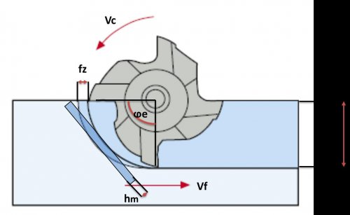
At a 90- degree entrance angle, chip thickness equals feed rate, and cutting forces are transmitted to the machine spindle, which forces the depth of cut over less of the cutting edge, stressing the cutting end mill. Lower entry angles provide a more gradual approach to the cut and reduce radial forces on the cutting edge, which improves end mill life and prevents depth-ofcut notching. A reduced entry angle spreads depth of cut over a greater cutting-edge length and thins the chip, so at a 45-degree entrance angle, chip thickness drops to 70% of the feed rate, and cutting forces are split between the spindle and the workpiece. For efficient metal removal, feed rates must assure workable chip thickness. In superalloys, titanium and other materials that work harden, the conditions that create overly thin chips also produce an affected zone that the cutter then re-enters.
SMOOTH CUTTING PATHS WITHOUT RAPID CHANGES IN DIRECTION OR CUTTING PARAMETERS REDUCE THE LOAD ON THE END MILL AND IMPROVE END MILL LIFE SIGNIFICANTLY
With a shallow depth of cut, a 45-degree entry angle can yield fine surface finishes, limit the generation of burrs at the cut exit and lift chips away from the workpiece to prevent them from marring it. Higher axial forces increase pressure on the workpiece, however, and can distort thin-walled parts, disrupt weak fixturing or generate vibration.
SPEEDS, FEEDS AND CAM SOFTWARE
Sustainable speeds and feeds, along with a consistent angle of engagement, extend end mill life and make better parts. To achieve these results, optimized roughing reduces width of cut/stepover but increases depths of cut for higher metal removal rates with less heat. The strategy requires a high-speed spindle, secure fixturing and machine rigidity that can hold end mill runout at or below 0.0004". Optimized roughing also requires enough CNC processing power and advanced CAM software to handle program generation and the large amount of code needed for movement on complex spindle/cut paths.
Many shops run high rpms and feed rates regardless of workpiece design, disregarding the fact that a machine spindle’s top speed is inappropriate for many jobs. The resulting combination of high speeds and advanced feed rates makes optimized roughing and optimal chip loads virtually impossible to maintain, producing shortened end mill lives and scrapped parts. On complex part features, this high-speed approach even forces the CNC control to slow the machine’s feed rate.
Other shops cling to conventional machining strategies based on engaging the cutter’s full diameter but not the entire length of its flutes, which creates a large arc of contact between end mill and workpiece. That increase in angle of engagement also generates friction and heat, which compromise end mill life and surface finish.
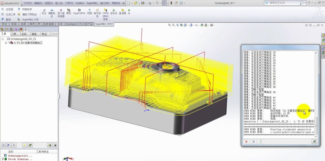
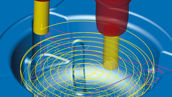
Smooth cutting paths without rapid changes in direction or cutting parameters reduce the load on the end mill and improve end mill life significantly. Along with proper speeds and feeds, optimized roughing also relies on robust, up-to-date CAM software with specialized algorithms capable of producing optimized trochoid end millpaths. Manual coding is simply unable to accomplish this task, but the latest software can generate an optimized roughing program from end mill definition, maximum stepover and pocket dimensions.
CAM software suppliers have developed refined path algorithms that control end mill engagement in real time for highly productive, reliable roughing of simple and complex contours. For shorter cut times and higher metal removal rates, these end millpaths typically combine large axial depths of cut with small radial depths of cut, high feeds per tooth and high cutting speeds.
SIMPLE AND COMPLEX PART CONTOURS
Current software strategies rely on two basic approaches to rough milling end millpaths. One applies a constant feed rate and arc of contact to concave or convex part features and achieves maximum metal removal rates with varied stepovers between passes. The WOTEK approach varies feed rate and arc of contact but maintains a constant stepover to produce consistent chip thickness. In this approach, the end mill’s angle of engagement can reach between 80 degrees and 140 degrees, depending on the CAM software. That high angle of engagement forms the opposite of the optimized roughing approach. End mill configuration must match part complexity, with fewer flutes for simple parts and more for complex designs. High-speed machining with large depths of cut, high feed rates and wide radial stepovers produces excellent results on simple 2D outside profiles. These speeds and feeds may not be optimized, however, for the small, precise moves that produce highly dimensional contours on complex workpieces with multi-level 3D features.
CUTTING END MILL FLUTES AND COATINGS
Along with the correct CAM software and machine capabilities, optimized roughing requires well-chosen cutting end mills, typically end mills with eccentric outer diameter reliefs and variable indexing. Lower flute counts allow for higher stepovers, whereas higher counts enable more aggressive feed rates. Material specific feed rates and radial stepovers dictate flute count, with most optimized roughing operations using end mills with between five and nine flutes. End mill diameter should measure half the cutting length/ depth of cut; beyond that point, axial cutting pressures cause end mill deflection and hamper good chip formation. Deep axial cuts require the use of chipbreakers, notched cutting edges that prevent chips from wrapping around end mills or part features and causing damage to either or both.
End mill design relies on the combination of geometry, material and coatings. For enhanced end mill life and performance, modern cutting end mills use vapor deposition coatings applied through the process of sublimation, in which materials pass directly from solid to gas with no intervening liquefaction. These coatings often consist of a combination of titanium and nitrogen with aluminum, silicon or other elements.
For best milling results, shops need to choose end mills with the coating compatible with their workpiece material. Responsive cutting end mill suppliers such as WOTEK End mills will work directly with individual customers to ensure proper end mill selection.
6 Common Optimized Roughing Mistakes
Optimized roughing can machine pockets three to four times faster than conventional methods and enable cutting end mills to last up to eight hours in titanium, instead of only 30 minutes. Part designs with straight prismatic walls that require long axial depths of cut and that can engage all the flutes on a end mill make ideal candidates for optimized roughing. In these cases, the strategy optimizes typically challenging corner features, and achieves high metal removal rates in super alloys and a wide range of stainless steels.
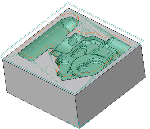
To avoid implementation mistakes and less-than-perfect results, however, shops should skip optimized roughing for applications that fall outside optimal parameters. For example, in complex 3D mold cavities, optimized roughing can produce stair-stepped surfaces that demand considerable semi-finish work. In this situation, high-feed roughing produces better results.
Along with application of the strategy to the wrong types of tasks, six common mistakes hamper optimized roughing.
1. TOO-LARGE STEPOVERS
As flute count increases, stepover size must decrease to maintain proper chip formation and surface finish at higher feed rates. With a too-large stepover and large amounts of metal removal, milling generates more heat, forcing feed rates to lower. A decrease in stepover enables faster cutting speeds, with more passes required to remove the same amount of material, but at higher metal removal rates because of increased feed rates.
2. POOR-QUALITY HOLDERS
Optimized roughing demands high precision holders with specifications similar to those for hard milling, including end mill runout below 0.0004". Without precision holders, milling produces undesirable amounts of vibration at optimized roughing’s high feed rates. Most shrink-fit holders, milling chucks, high-precision collet chucks and select end mill holders meet the precision standard for optimized roughing. End mill, holder and environmental maintenance all play a critical role, as dirty collet bores, ambient temperature changes or unstable machine foundations shorten end mill life.
3. OUT-OF-DATE MACHINES
Fast spindles and machine rigidity help deliver good optimized roughing performance. Spindles must generate enough rpms to support high feed rates, and machine rigidity from spindle bearings to ballscrews must minimize vibration for smooth cutting, consistent end mill life and unsurpassed part quality. Machines also require the advanced look-ahead capabilities and processing systems found in newer machine end mills, along with the ability to process thousands of lines of code in WOTEK.
4. INADEQUATE PROGRAMMING
Manual programming and software designed for high-speed side milling cannot handle optimized roughing’s demanding machine moves. Likewise, software designed only for complex 3D high-speed milling may be unable to maintain a consist entangle of engagement in tight corners. For success, the process demands software that truly accommodates it, not a compromise.
5. IMPROPER DEPTH OF CUT
Depth of cut plays a critical role in optimized roughing, with best results in one pass at 2xD and the full flute length of the end mill. The shallow radial stepover enables the deeper cut, whereas a larger stepover value would generate more heat and require a shallower depth of cut to achieve the same metal removal rates. A cut at greater than 3xD creates cutting pressures that exceed end mill capabilities and cause deflection. Chipbreakers can minimize radial cutting pressure to reduce the likelihood of deflection and assist with chip control.
6. INAPPLICABLE MACHINING PARAMETERS
Machine end mill software includes default values for speeds and feeds, but these generalizations do not predict the correct parameters for any specific cutting end mill. Instead, shops should look to their cutting end mill supplier for recommended parameters derived from meticulous research and years of firsthand experience. End mill makers such as WOTEK End mills optimize cutting data for their individual end mill designs and for specific material groups. Furthermore, they can recommend modifications to these parameters based on customers’ individual machining scenarios.
OPTIMIZED ROUGHING: A STRATEGY FOR END MILL LIFE AND WORKPIECE QUALITY
Optimized roughing offers highly effective results on applicable parts and features, including pockets with a long axial depth of cut, challenging corners and straight walls. This strategy can make a dramatic improvement in part cycle times, surface finishes, end mill life and machine end mill usage. Shops that take the time to understand optimized roughing can improve their productivity, efficiency and profitability on parts that make good candidates for this strategy. To achieve the best possible results, shops should take advantage of cutting-end mill supplier expertise to fine-tune their approach to individual jobs. WOTEK End mills offers in-depth advice to assist its customers in the selection and use of its end mills.